
Calibration method of fiber grating pressure sensor

A pressure sensor and fiber grating technology, which is applied in the field of optoelectronic measurement devices, can solve problems such as poor adaptability and the accuracy of calibration results needs to be improved, and achieves the effect of high work efficiency and simple operation.

Inactive Publication Date: 2016-06-29
YUNNAN POWER GRID CO LTD ELECTRIC POWER RES INST
View PDF8 Cites 14 Cited by
  • Summary
  • Abstract
  • Description
  • Claims
  • Application Information

AI Technical Summary

Problems solved by technology

However, this kind of calibration device and calibration method has poor adaptability, and the accuracy of the calibration results needs to be improved.

Method used


Image

  • Calibration method of fiber grating pressure sensor
  • Calibration method of fiber grating pressure sensor
  • Calibration method of fiber grating pressure sensor

Examples


Embodiment Construction

[0029] An embodiment of the present invention provides a calibration method for a fiber grating pressure sensor to provide a more comprehensive and accurate calibration conclusion.

[0030] In order to enable those skilled in the art to better understand the technical solutions in this description, the technical solutions in this description embodiment will be clearly and completely described below in conjunction with the drawings in this description embodiment. Obviously, the described The embodiments are only some of the embodiments of this description, not all of them. Based on the embodiments in this description, all other embodiments obtained by persons of ordinary skill in the art without creative efforts shall fall within the protection scope of this description.

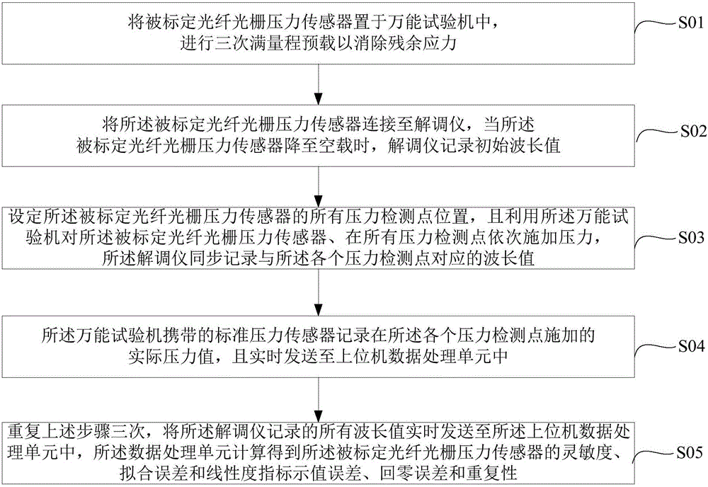
[0031] Please refer to accompanying drawing 1, this figure has shown the calibration method of a kind of fiber grating pressure sensor provided by the present invention, as shown in the figure, comprises the ...


PUM


Abstract

The invention discloses a calibration method of an optical fiber grating pressure sensor, comprising the following steps: placing the optical fiber grating pressure sensor to be calibrated in a universal testing machine, and carrying out three full-scale preloads; connecting the optical fiber grating pressure sensor to be calibrated to a demodulator instrument, when it drops to no-load, the demodulator records the initial wavelength value; set the position of all pressure detection points of the calibrated fiber grating pressure sensor, and use the universal testing machine to apply pressure to it, and the demodulator records synchronously with each The wavelength value corresponding to the pressure detection point; the standard pressure sensor carried by the universal testing machine records the actual pressure value applied at each pressure detection point, and sends it to the host computer data processing unit in real time; repeat the above steps three times, and the demodulator records All wavelength values ​​are sent to the host computer data processing unit in real time, and the sensitivity, fitting error, linearity indication error, zero return error and repeatability index of the calibrated fiber grating pressure sensor are calculated.

Description

technical field [0001] The invention relates to the technical field of optoelectronic measuring devices, in particular to a calibration method for an optical fiber grating pressure sensor. Background technique [0002] Fiber Bragg grating sensors are widely used in power system monitoring due to their strong anti-electromagnetic interference and low transmission loss. In order to ensure the accuracy of monitoring data and ensure engineering safety, the fiber grating sensor used must be calibrated and calibrated before use, otherwise large measurement errors will lead to serious safety and quality problems. Among them, there is a kind of fiber grating pressure sensor. In order to get an accurate calibration conclusion, the important factors such as pressure indication calibration, sensitivity, linearity, fitting error, indication error, zero return error and repeatability should be considered comprehensively. Calculation of static calibration coefficients. [0003] However,...

Claims


Application Information

Patent Timeline
Patent Type & Authority Applications(China)
IPC IPC(8): G01L25/00
CPCG01L25/00
Inventor 王恩曹敏李博唐标翟少磊李川
Owner YUNNAN POWER GRID CO LTD ELECTRIC POWER RES INST
Learn More