Method for improving strength of ruggedized computer plastic structural member and plastic structural member

A technology for strengthening computers and structural parts. It is used in computing, digital data processing parts, instruments, etc. It can solve problems such as poor strength, and achieve the effects of convenient use, light weight and improved strength.

Inactive Publication Date: 2016-06-29
SHANDONG CHAOYUE DATA CONTROL ELECTRONICS CO LTD
View PDF3 Cites 0 Cited by
  • Summary
  • Abstract
  • Description
  • Claims
  • Application Information

AI Technical Summary

Problems solved by technology

[0003] Due to the portability and processability of plastic, it is not only used in daily life, but also gradually promoted and used in the field of reinforced computers; however, compared with metal, the strength of plastics is poor, and reinforced computers need to adapt and To meet the harsh environmental requirements, such as vibration and shock, high and low temperature, and damp heat, etc., in order to make the plastic casing meet the requirements of vibration and shock, the strength of the plastic parts must be increased

Method used


Image

  • Method for improving strength of ruggedized computer plastic structural member and plastic structural member
  • Method for improving strength of ruggedized computer plastic structural member and plastic structural member
  • Method for improving strength of ruggedized computer plastic structural member and plastic structural member

Examples


Embodiment 1

[0032] A method for increasing and strengthening the strength of computer plastic structural parts of the present invention comprises the following steps:

[0033] (1) By opening a groove on the surface of the non-mold plastic structural part with a thinner wall thickness, that is, on the surface of the weaker plastic structural part, and opening a limited slot in the groove;

[0034] (2) Install the bead in the groove in step (1), and process the limit platform on the inner surface of the bead, that is, the surface matching with the groove;

[0035] (3) When assembling the groove in step (1) and the bead in step (2), fix it by dispensing glue and positioning the bumps, that is, add glue in the limit groove, and then connect the limit table with the limit The grooves are clicked and matched to complete the assembly of the bead and the groove, and do glue dispensing on the mating surface after the assembly is completed. The bead is made of aluminum alloy or spring steel.

Embodiment 2

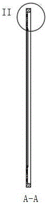
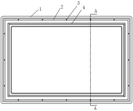
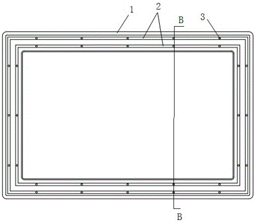
[0037] as attached Figure 1-8 As shown, the plastic structural part of the present invention adopts the plastic structural part 1 prepared by the method described in Example 1. A circle of grooves 2 is arranged on one side surface of the plastic structural part 1, and the bottom of the groove 2 is provided with a uniform The limit groove 3 is arranged, and the bead 4 is arranged in the groove 2. On one side of the bead 4, a uniformly arranged limit platform 5 is arranged. The limit platform 5 is cylindrical, and the limit platform 5 is clamped with the limit groove 3 Cooperate. The bead 4 is made of aluminum alloy or spring steel. There are five limiting grooves 3 in the length direction of the plastic structural member 1, and three limiting grooves 3 in the width direction. The number of limiting platforms 5 is less than or equal to the number of limiting slots 3 .


PUM


Abstract

The invention discloses a method for improving the strength of a ruggedized computer plastic structural member and a plastic structural member and belongs to the field of ruggedized computers.The method aims to produce a non-mold plastic structural member on the premise that machining cost is low, machining efficiency is high and plastic strength is improved.According to the technical scheme, the method comprises the steps of 1, forming grooves in the surface, with a thin wall, namely poor strength, of the non-mold plastic structural member, and forming a limiting slot in each groove; 2, installing a depression bar in each groove obtained in the step 1, and machining a limiting boss on the inner surface, matched with the corresponding groove, of each depression bar.The plastic structural member is obtained with the method, a circle of grooves are formed in the surface of one side of the plastic structural member, a plurality of limiting slots are formed in the bottoms of the grooves, and the depression bars are arranged in the grooves.

Description

technical field [0001] The invention relates to the field of computer reinforcement, in particular to a method for increasing the strength of computer plastic structural parts and the plastic structural parts. Background technique [0002] Ruggedized computer (ruggedized computer) is to adapt to various harsh environments. During computer design, various factors that affect computer performance, such as system structure, electrical characteristics and mechanical physical structure, etc., take corresponding guarantee measures. Harsh environment computer. Its characteristics are: strong environmental adaptability, high reliability and high maintainability; strong real-time processing capability; serialization, standardization and modularization; the development of special software is the key to its application. [0003] Due to the portability and processability of plastic, it is not only used in daily life, but also gradually promoted and used in the field of reinforced compu...

Claims


Application Information

Patent Timeline
Patent Type & Authority Applications(China)
IPC IPC(8): G06F1/18
CPCG06F1/183
Inventor 王晓龙孙永升
Owner SHANDONG CHAOYUE DATA CONTROL ELECTRONICS CO LTD
Why Eureka
Try Eureka