Mechanism for dissociating battery cell winding needle and needle dissociating method for mechanism

A technology of coiling needles and batteries, which is applied to circuits, electrical components, secondary batteries, etc., can solve problems such as crashing separators, positive and negative electrodes, increased maintenance, and reduced tightness of winding cores. Unable to unwind the needle normally, high degree of automation, and the effect of improving production efficiency

Active Publication Date: 2016-06-29
DONGGUAN LIWINON ENERGY TECH
View PDF4 Cites 3 Cited by
  • Summary
  • Abstract
  • Description
  • Claims
  • Application Information

AI Technical Summary

Problems solved by technology

[0002] In the production process of lithium-ion batteries, there is a process of winding positive and negative electrodes and separators into winding cores. However, the winding mechanism in the existing automatic winding equipment mostly adopts a two-half needle winding structure. One half of the winding needles can move longitudinally forward and backward relative to the other half of the winding needles; one half is fixedly connected to the motor as the active winding needle, and the other half is used as the driven winding needle, which can move axially relative to the half connected to the motor, and it is completely possible Remove (take off), rotate and wind under the drive of the motor; there is a gap between the two halves of the winding needle, the diaphragm passes through the gap, and is wound together with the winding needle. The film and the diaphragm are wound together), and the winding needle is separated from the winding core; the separation film is tightly attached to and wrapped on the surface of the winding needle due to tension, and the material is thin and soft, and its thickness is usually i...

Method used


Image

  • Mechanism for dissociating battery cell winding needle and needle dissociating method for mechanism
  • Mechanism for dissociating battery cell winding needle and needle dissociating method for mechanism
  • Mechanism for dissociating battery cell winding needle and needle dissociating method for mechanism

Examples


Embodiment Construction

[0038] The present invention and its beneficial effects will be described in further detail below in conjunction with specific embodiments and accompanying drawings, but the specific embodiments of the present invention are not limited thereto.

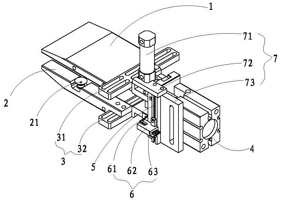
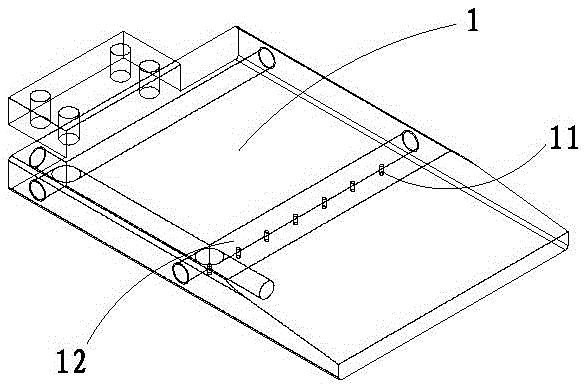
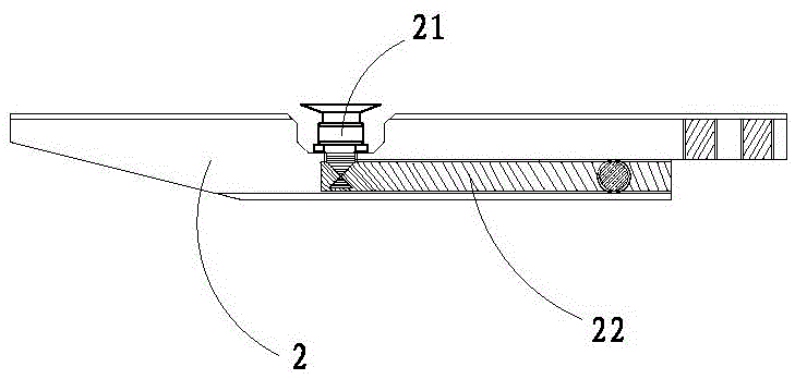
[0039] Such as Figure 1~6 As shown, a mechanism for pulling out the needle of the battery core, including a first discharge clamp 1, a second discharge clamp 2 corresponding to the first discharge clamp 1, a finger connector 3, and a finger cylinder 4. The fixed seat 5 arranged between the clamp finger connector 3 and the clamp finger cylinder 4, and the photoelectric control unit 6 and the limit control unit 7 installed on the fixed seat 5, the first discharge clamp 1, the second discharge clamp The clamps 2 are respectively connected to the clamp finger cylinder 4 through the clamp finger connector 3, the first discharge clamp 1 is provided with a vacuum suction hole 11, the second discharge clamp 2 is provided with a vacuum suctio...


PUM


Abstract

The invention belongs to the technical field of manufacturing of lithium-ion batteries, and particularly relates to a mechanism for dissociating a battery cell winding needle and a needle dissociating method for the mechanism. The mechanism comprises a first discharge clamp, a second discharge clamp, a finger-clamping connector, a finger-clamping cylinder, a fixed seat, a photoelectric control unit and a limiting control unit, wherein the second discharge clamp is arranged corresponding to the first discharge clamp; the fixed seat is arranged between the finger-clamping connector and the finger-clamping cylinder; the photoelectric control unit and the limiting control unit are arranged on the fixed seat; the first discharge clamp and the second discharge clamp are connected with the finger-clamping cylinder through the finger-clamping connector respectively; vacuum suction holes are formed in the first discharge clamp; vacuum suction nozzles are arranged on the second discharge clamp; and the vacuum suction holes are arranged corresponding to the vacuum suction nozzles. Compared with the prior art, the yield of a battery cell can be improved; the problem that an isolating film is scrapped due to cell dissociation can be reduced; and the condition that a winding machine further works after a needle dissociating failure of the winded cell is avoided.

Description

technical field [0001] The invention belongs to the technical field of lithium-ion battery manufacturing, and in particular relates to a mechanism and a needle-drawing method for pulling out a battery core winding needle. Background technique [0002] In the production process of lithium-ion batteries, there is a process of winding positive and negative electrodes and separators into winding cores. However, the winding mechanism in the existing automatic winding equipment mostly adopts a two-half needle winding structure. One half of the winding needles can move longitudinally forward and backward relative to the other half of the winding needles; one half is fixedly connected to the motor as the active winding needle, and the other half is used as the driven winding needle, which can move axially relative to the half connected to the motor, and it is completely possible Remove (take off), rotate and wind under the drive of the motor; there is a gap between the two halves of...

Claims


Application Information

Patent Timeline
IPC IPC(8): H01M10/0587
CPCH01M10/0587Y02E60/10Y02P70/50
Inventor 叶海军王威李载波杨山郑明清
Owner DONGGUAN LIWINON ENERGY TECH
Why Eureka
Try Eureka