Cutting blender mixer with unloading, pressing, and filtering used for hay

A technology of mixer and forage, applied in cutting equipment, application, agricultural machinery and implements, etc., can solve the problems of affecting work, different lengths of forage, etc., and achieve the effect of improving efficiency, improving collection efficiency and convenient operation.

Inactive Publication Date: 2016-07-06
CHONGQING NENGKAI TECH CO LTD
View PDF0 Cites 4 Cited by
  • Summary
  • Abstract
  • Description
  • Claims
  • Application Information

AI Technical Summary

Problems solved by technology

[0004] During the application, it was found that there were still deficiencies. Sometimes the length of the grass after cutting was different, which would affect the next work.

Method used


Image

  • Cutting blender mixer with unloading, pressing, and filtering used for hay
  • Cutting blender mixer with unloading, pressing, and filtering used for hay

Examples


Embodiment 1

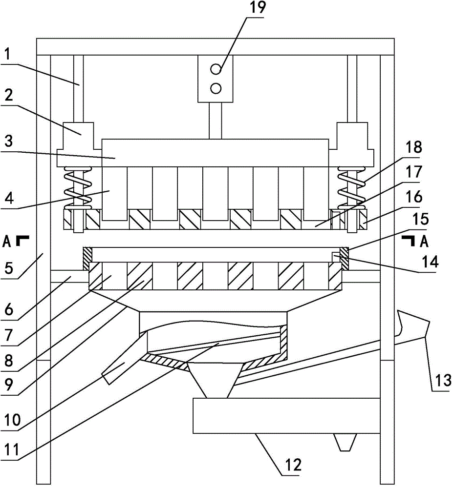
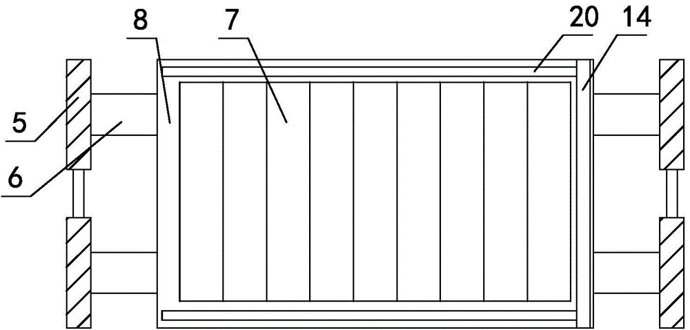
[0024] Such as figure 1 , figure 2 As shown, the cutting and mixing machine for discharging, pressing, and filtering forage includes a bracket 5 with a gate structure as a whole. In the bracket 5, a movable knife and a static knife that cut and cooperate with each other are sequentially arranged from top to bottom. The movable knife Including the knife holder 3, a number of cutter heads 4 are installed at the bottom of the knife holder 3, the top of the knife holder 3 is connected with a power mechanism 19 for the knife holder 3 to move up and down, the power mechanism 19 is fixed on the top of the bracket 5, the static knife includes a static knife plate 8. The static knife plate 8 is provided with a knife hole 7 communicating up and down and matching with the cutting head 4, the static knife plate 8 is set on the bracket 5, and the top of the static knife plate 8 is provided with left and right edges along the upper surface of the static knife plate 8. Sliding slide plate 14...

Embodiment 2

[0028] A further change is made on the basis of the first embodiment. The power mechanism 19 is changed into a cylinder, the cylinder is fixed on the bracket 5, and the piston rod is connected to the tool holder 3. Others are the same as in Example 1.

Embodiment 3

[0030] Further changes are made on the basis of the first embodiment, and the power mechanism 19 is changed. The power mechanism 19 includes a screw and a nut that cooperate with each other. The lower end of the screw is fixed on the tool holder 3, and the nut is movably installed on the bracket 5, and the nut Only free rotation can be done on the bracket 5, and the nut is driven by a gear set. Others are the same as in Example 1.


PUM


Abstract

The invention relates to a cutting blender mixer with unloading, pressing, and filtering used for hay, and belongs to the technical field of hay cutting. The cutting blender mixer comprises a support. The support is internally provided with a moving blade and a static blade. The moving blade comprises a tool apron. The bottom of the tool apron is provided with a plurality of cutting heads. The top of the tool apron is connected with a power mechanism used for the tool apron to move up and down. The power mechanism is fixed on the top of the support. The static blade comprises a static blade board. The static blade board is provided with tool bores. The static blade board is arranged on the support. The top of the static blade board is provided with a sliding plate which slides left and right along the upper surface of the static blade board. A pressing plate is arranged below the tool apron. The periphery of the static blade board is sleeved with a sheath which provides convenience for laying hay. A classifying tank is arranged below the static blade board. The classifying tank is internally provided with a filter screen. The filter screen divides the classifying tank into a coarse material region and a fine material region. The outlet of the fine material region is provided with a blender. The cutting blender mixer can perform classifying processing on the hay when cutting the hay, and qualified hay enters the next operation. The cutting blender mixer is convenient to operate.

Description

Technical field [0001] The invention relates to a cutting and mixing machine for discharging, pressing and filtering forage, belonging to the technical field of forage cutting. Background technique [0002] At present, the forages fed to pigs, cattle, sheep, horses, etc. all need to be cut, and some of the cut forages are mixed with processed feed to increase their appetite. At present, the commonly used cutting method is to use manual or cutting corn stalks and other equipment. With the continuous improvement of people's living standards, the demand for pork, cattle, sheep, and horse meat is also increasing, especially for barbecues and banquets. For this reason, the amount of feeding is getting larger and larger, and the human-style cutting of forage can no longer meet the requirements well, and the labor cost is very high; the equipment cost of the usual cutting machine is higher, and the investment is slow. [0003] In the previous month, the inventor designed a complete set ...

Claims


Application Information

Patent Timeline
Patent Type & Authority Applications(China)
IPC IPC(8): A01F29/08A01F29/09
Inventor 周世平
Owner CHONGQING NENGKAI TECH CO LTD
Why Eureka
Try Eureka