Supercharge Your Innovation With Domain-Expert AI Agents!

Mechanical arm cleaning device based on computer

A cleaning device and computer technology, applied in the direction of liquid cleaning method, dryer, drying gas arrangement, etc., can solve the problems of poor cleaning effect, inability to rotate workpieces at multiple angles, and inability to clean all holes and surfaces, etc., to achieve The effect of reducing the floor space and facilitating the operation of workers

Inactive Publication Date: 2016-07-06
LINKRUN TIANJIN TECH CO LTD
View PDF0 Cites 2 Cited by
  • Summary
  • Abstract
  • Description
  • Claims
  • Application Information

AI Technical Summary

Problems solved by technology

[0003] In order to solve the problem that the existing cleaning device cannot rotate the workpiece at multiple angles, cannot clean all the holes and surfaces, and has poor cleaning effect when cleaning the workpiece, the present invention further proposes a computer-controlled mechanical arm cleaning device

Method used


Image

  • Mechanical arm cleaning device based on computer
  • Mechanical arm cleaning device based on computer
  • Mechanical arm cleaning device based on computer

Examples


specific Embodiment approach 1

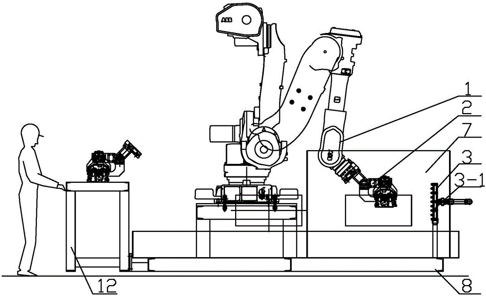
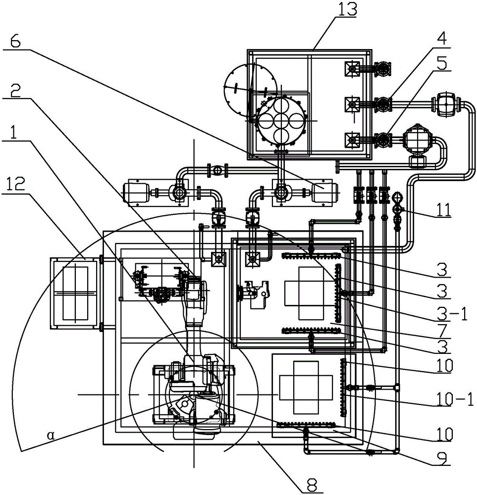
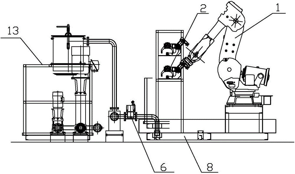
[0007] Specific implementation mode one: as Figure 1-6 As shown, a computer-controlled mechanical arm cleaning device described in this embodiment includes a six-axis mechanical arm 1, a turbulent flow cleaning pump 4, a fixed-point positioning cleaning pump 5 and a water tank 13, and the inlet end of the fixed-point positioning cleaning pump 5 It communicates with the water tank 13, and also includes a fixture 2, a plurality of cleaning plates 3, a cleaning chamber 7 and a workbench 8. The root end of the six-axis mechanical arm 1 is fixedly installed on the workbench 8, and the six-axis mechanical arm 1 The end is connected with the fixture 2, the cleaning chamber 7 is fixedly installed on the workbench 8, and it is ensured that the end of the six-axis robotic arm 1 can extend into the cleaning chamber 7 after the six-axis robotic arm 1 is deployed, and multiple cleaning plates 3 are arranged on the On the inner side wall of the cleaning chamber 7 or on the inner side wall ...

specific Embodiment approach 2

[0009] Specific implementation mode two: as Figure 1-6 As shown, the computer-controlled mechanical arm cleaning device in this embodiment also includes a drying chamber 9, two drying plates 10 and an air compressor 11, and the drying chamber 9 is fixedly installed on the workbench 8 , two drying boards 10 are located in the drying chamber 9, and the two drying boards 10 are arranged in an L shape, each drying board 10 is provided with several drying nozzles 10-1, each drying board The drying nozzle 10-1 on the 10 is connected with the output end of the air compressor 11 through a pipeline. This embodiment ensures that after the workpiece is cleaned, it can be sent into the drying chamber 9 by the six-axis mechanical arm 1 and quickly dried by the drying nozzle 10 - 1 on the drying plate 10 . Other components and connections are the same as those in the first embodiment.

specific Embodiment approach 3

[0010] Specific implementation mode three: as Figure 1-6 As shown, three cleaning boards 3 are arranged in the cleaning chamber 7 of the computer-controlled robotic arm cleaning device in this embodiment, and each cleaning board 3 is fixedly installed on an inner side wall of the cleaning chamber 7 . The cleaning nozzles 3-1 are densely arranged and can clean the workpiece thoroughly during the movement of the workpiece. Other components and connections are the same as those in the first embodiment.


PUM


Abstract

The invention discloses a mechanical arm cleaning device based on a computer, and particularly relates to a mechanical arm cleaning device based on computer control. In order to solve the problems that a workpiece cannot realize multi-angle rotation, all holes and surfaces of the workpiece cannot be cleaned, and the cooling effect is poort when a current cleaning device is used for cleaning the workpiece, the mechanical arm cleaning device based on the computer comprises a six-axis mechanical arm, a turbulent-flow cleaning pump, a fixed-point positioned cleaning pump and a water tank, and further comprises a clamp, a plurality of cleaning boards, a cleaning room and a workbench, wherein the inlet end of the fixed-point positioned cleaning pump communicates with the water tank; the root end of the six-axis mechanical arm is fixedly mounted on the workbench; the tail end of the six-axis mechanical arm is connected to the clamp; the cleaning room is fixedly mounted on the workbench; a plurality of cleaning spray heads are arranged on each cleaning board; the cleaning spray heads on each cleaning board are connected to the outlet end of the fixed-point positioned cleaning pump through a pipeline; and the cleaning room is connected to the outlet end of the turbulent-flow cleaning pump through a pipeline. The mechanical arm cleaning device belongs to the field of computer control.

Description

Technical field [0001] The invention involves a cleaning device based on computer control, which specifically involves a computer -based machine -controlled cleaning device, which is a computer control field. Background technique [0002] After the mechanical workpiece is processed on the production line, the workpiece needs to be cleaned. At present, when the existing equipment is cleaning the workpiece, it is just to rotate the workpiece in the water or spray water spraying mechanism to rotate the water.Therefore, during the cleaning process, all the holes and surfaces of the workpiece cannot be cleaned, and the structure of each workpiece is different. Different workpieces need to use different cleaning equipment, and the existing cleaning equipment occupies a large area, which is reduced, which is reduced, which is reduced.Operating space in the workshop. Invention content [0003] In order to solve the existing cleaning device when cleaning the workpiece, the workpiece cann...

Claims


Application Information

Patent Timeline
Patent Type & Authority Applications(China)
IPC IPC(8): B08B3/10B08B3/02F26B11/00F26B21/00
CPCB08B3/10B08B3/02B08B3/022B08B3/041F26B11/00F26B21/004
Inventor 张鹏
Owner LINKRUN TIANJIN TECH CO LTD
Features
  • R&D
  • Intellectual Property
  • Life Sciences
  • Materials
  • Tech Scout
  • Unparalleled Data Quality
  • Higher Quality Content
  • 60% Fewer Hallucinations
Learn More