Passive spring roller hemming component

A passive, hemming technology, applied in metal processing, metal processing equipment, manufacturing tools, etc., can solve the problems of rigid system impact and wear, adverse effects of hemming quality, complex airbag buffer system, etc., to achieve accurate movement position and speed, energy saving Good effect and simple structure

Inactive Publication Date: 2016-07-06
WUHAN DEBAO EQUIP CO LTD
View PDF4 Cites 3 Cited by
  • Summary
  • Abstract
  • Description
  • Claims
  • Application Information

AI Technical Summary

Problems solved by technology

The roller system usually adopts spring buffer system, airbag buffer system and rigid system, etc., but the general spring buffer system is prone to defects such as unstable rolling pressure, difficult debugging, and high cost; Large, large interference area; rigid system is prone to impact and wear, which will adversely affect the quality of hemming after a long period of use

Method used


Image

  • Passive spring roller hemming component
  • Passive spring roller hemming component
  • Passive spring roller hemming component

Examples


Embodiment 1

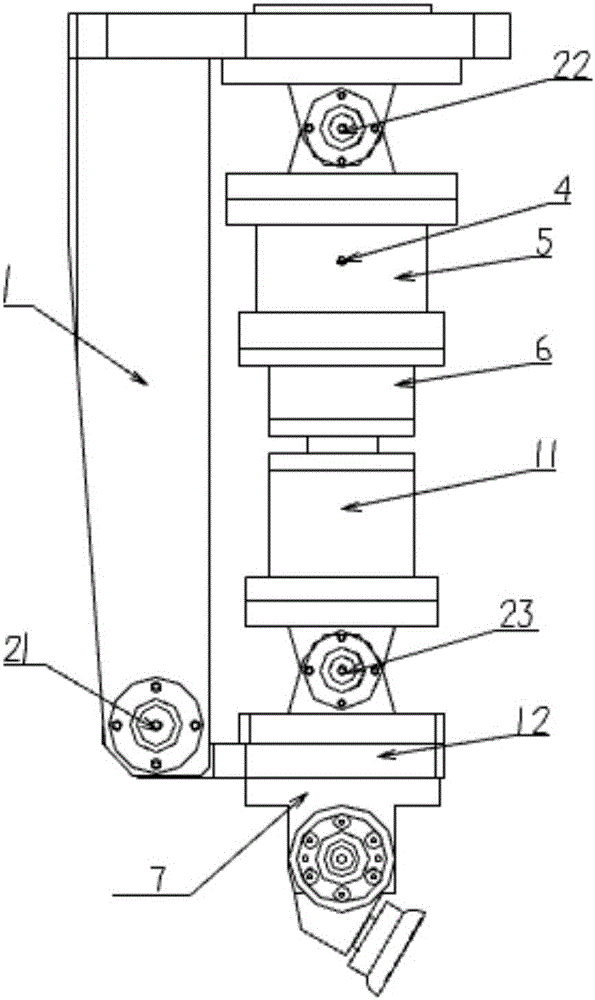
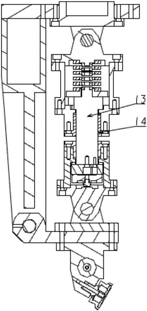
[0041] Such as Figure 1-3 As shown, a passive spring hemming assembly is in contact with the body of the car to be hemmed, including:

[0042] Support 1, its top is provided with the flange top cover 3 that links to each other with mechanical arm, and the bottom is hinged with base plate 12 by first hinge 21, and described flange top cover 3 and described bottom plate 12 are parallel and oppositely arranged;

[0043] A spring buffer 5, which is arranged between the flange top cover 3 and the bottom plate 12, and the upper part of the spring buffer 5 is hinged with the flange top cover 3 through a second hinge 22;

[0044] Cylinder 6, which is arranged between the spring buffer 5 and the bottom plate 12, the upper part of the cylinder 6 is connected with the lower part of the spring buffer 5, and the cylinder 6 has a seat for accommodating the guide rod 13 In the inner space, the upper end of the guide rod 13 is in conflict with the spring buffer 5, and the lower end of the c...

Embodiment 2

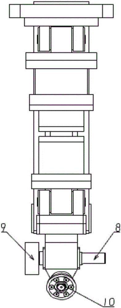
[0053] Such as Figure 4-6 As shown, a passive spring hemming assembly is in contact with the body of the car to be hemmed, including:

[0054] Support 1, the upper part of which is provided with a flange top cover 3 connected to the mechanical arm, which is perpendicular to the plane where the support 1 is located;

[0055] A spring buffer 5, which is arranged below the flange top cover 3, and the upper part of the spring buffer 5 is hinged with the flange top cover 3 through a fourth hinge 24;

[0056] Cylinder 6, which is arranged below the spring buffer 5, the upper part of the cylinder 6 is connected with the lower part of the spring buffer 5, the cylinder 6 has an inner space for accommodating the guide rod 61, the guide The upper end of the rod 61 interferes with the spring buffer 5; and

[0057] The second piping body 7, which is arranged below the cylindrical body, the upper part of the second piping body 7 and the bottom of the cylindrical body 6 are hinged by the ...


PUM


Abstract

The invention discloses a passive spring hemming assembly, which is in contact with the plate body to be hemmed of the automobile, and includes a bracket, the upper part of which is provided with a flange top cover connected with a mechanical arm, and the lower part is hinged with the bottom plate through a first hinge; a spring buffer , which is arranged between the flange top cover and the bottom plate; a cylinder, which is arranged between the spring buffer and the bottom plate, and the upper part of the cylinder is connected with the lower part of the spring buffer , the cylinder has an inner space for accommodating the guide rod, the upper end of the guide rod is in conflict with the spring buffer; the first rolling body is arranged on the lower part of the bottom plate, and the first rolling body includes multiple rollers of different shapes. The invention has the advantages of stable rolling force, simple debugging, low cost and the like.

Description

technical field [0001] The present invention relates to clamps for use in automobile manufacturing, and more particularly, the present invention relates to a passive spring hemming assembly. Background technique [0002] Car door cover hemming technology has now become an important process in the automobile manufacturing process. The application of hemming technology in the car body mainly includes car doors, machine covers, fenders and sunroof top covers, etc., and the hemming of door cover lines The methods mainly include press molding edging, desktop edging machine edging and robot rolling edging. Robot hemming technology is a new type of hemming technology, which has remarkable characteristics such as beautiful shape, easy realization of flexible production, low investment and maintenance costs, small working area, stable hemming quality and relatively short commissioning cycle. [0003] At present, the rollers in the robot hemming equipment are directly in contact with...

Claims


Application Information

Patent Timeline
Patent Type & Authority Applications(China)
IPC IPC(8): B21D19/14B21C51/00
CPCB21D19/14B21C51/00
Inventor 占朝阳
Owner WUHAN DEBAO EQUIP CO LTD
Why Eureka
Try Eureka