
Automatic return guide positioning mechanism

A technology of guiding positioning and automatic return, applied in positioning devices, metal processing equipment, feeding devices, etc., can solve the problems of poor precision of stamped products, deviation of workpieces, poor positioning effect, etc., to reduce impact, The positioning process is stable and reliable, and the effect of long service life

Inactive Publication Date: 2016-07-06
TIANJIN XINMAO TIANHE ELECTROMECHANICAL SCI & TECH CO LTD
View PDF5 Cites 1 Cited by
  • Summary
  • Abstract
  • Description
  • Claims
  • Application Information

AI Technical Summary

Problems solved by technology

[0002] In the production process of mold stamping, it is necessary to transfer the workpiece to the required position through the conveying equipment such as the conveyor belt, and then control the stamping equipment for production and processing. During the transmission process, the workpiece will inevitably shift. If the positioning of the workpiece is not taken effectively measures, then the precision of stamping products is poor and the pass rate is low
Ordinary positioning block or positioning plate can also play a role in positioning the workpiece to a certain extent, but the positioning effect is poor and difficult to adjust, so it is not suitable for working conditions with high processing requirements

Method used


Image

  • Automatic return guide positioning mechanism
  • Automatic return guide positioning mechanism

Examples


Embodiment Construction

[0021] It should be noted that, in the case of no conflict, the embodiments of the present invention and the features in the embodiments can be combined with each other.

[0022] In describing the present invention, it should be understood that the terms "center", "longitudinal", "transverse", "upper", "lower", "front", "rear", "left", "right", The orientations or positional relationships indicated by "vertical", "horizontal", "top", "bottom", "inner", "outer", etc. are based on the orientation or positional relationships shown in the drawings, and are only for the convenience of describing the present invention Creation and simplification of description, rather than indicating or implying that the device or element referred to must have a specific orientation, be constructed and operate in a specific orientation, and therefore should not be construed as limiting the invention. In addition, the terms "first", "second", etc. are used for descriptive purposes only, and should no...


PUM


Abstract

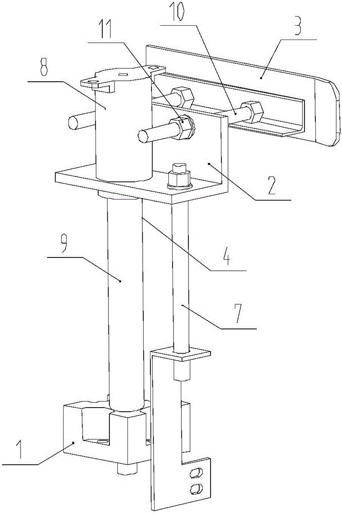
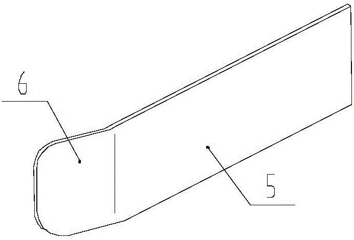
The invention provides an automatic return guide positioning mechanism. The automatic return guide positioning mechanism comprises a base, an installation frame, a material guide plate and a reset mechanism which is arranged on the base and used for driving the installation frame to be reset. The material guide plate is fixed to the installation frame through adjustable installation assemblies and provided with a material blocking surface in the vertical direction. A guide part is arranged in the position, in the material feeding direction, of one end of the material blocking surface. The installation frame is provided with a guide rod which is arranged vertically, and the lower end of the guide rod penetrates through the base and is in slide fit with the base. According to the automatic return guide positioning mechanism, the structural design is reasonable; the guide part is capable of playing a very good guide function and guiding a workpiece into a preset position, then the workpiece is reliably positioned through the material blocking surface of the material guide plate, and the whole positioning process is stable and reliable. A buffer pressure pad is arranged between a spring and the bottom of a sleeve, pressure is applied to the bottom of the sleeve through the buffer pressure pad, and load distribution is uniform; and meanwhile, impact of the spring on the bottom of the sleeve can be reduced, so that the sleeve pushing downwards process and the sleeve return process are more stable.

Description

technical field [0001] The invention belongs to the technical field of auxiliary devices for die stamping equipment, and in particular relates to a guiding and positioning mechanism for automatic return. Background technique [0002] In the production process of mold stamping, it is necessary to transfer the workpiece to the required position through the conveying equipment such as the conveyor belt, and then control the stamping equipment for production and processing. During the transmission process, the workpiece will inevitably shift. If the positioning of the workpiece is not taken effectively If the measures are adopted, then the precision of stamping products is poor and the pass rate is low. Ordinary positioning blocks or positioning plates can also play a role in positioning the workpiece to a certain extent, but the positioning effect is poor and difficult to adjust, so it is not suitable for working conditions with high processing requirements. Contents of the i...

Claims


Application Information

Patent Timeline
Patent Type & Authority Applications(China)
IPC IPC(8): B21D43/00
CPCB21D43/003
Inventor 赵宇志
Owner TIANJIN XINMAO TIANHE ELECTROMECHANICAL SCI & TECH CO LTD
Learn More