
Synchronous steel pipe drilling device with multiple actuating mechanisms

A multi-actuator and drilling device technology, applied in positioning devices, driving devices, feeding devices, etc., can solve the problems of easy distortion, accuracy dependent, time-consuming and labor-intensive, etc.

Inactive Publication Date: 2016-07-06
ANHUI QIFENG MACHINERY & EQUIP
View PDF8 Cites 29 Cited by
  • Summary
  • Abstract
  • Description
  • Claims
  • Application Information

AI Technical Summary

Problems solved by technology

[0002] The traditional drilling method is pole drilling, which has the disadvantages of cumbersome procedures, low dimensional accuracy, low processing efficiency, and prone to distortion, which directly affects the smooth progress of subsequent processes
Of course, drilling machines can also be used to drill holes in steel pipes. However, traditional drilling machines need to mark the parts of the steel pipes to be drilled in advance, and the accuracy of steel pipe drilling depends largely on the position accuracy of the parts to be drilled. , and once the drilling is completed, if drilling is still required, the drilling operation needs to be stopped, and the position of the steel pipe to be drilled should be marked again, which is time-consuming and laborious

Method used


Image

  • Synchronous steel pipe drilling device with multiple actuating mechanisms
  • Synchronous steel pipe drilling device with multiple actuating mechanisms
  • Synchronous steel pipe drilling device with multiple actuating mechanisms

Examples


Embodiment Construction

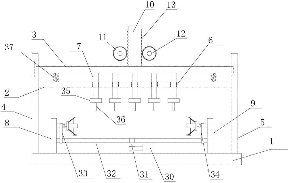
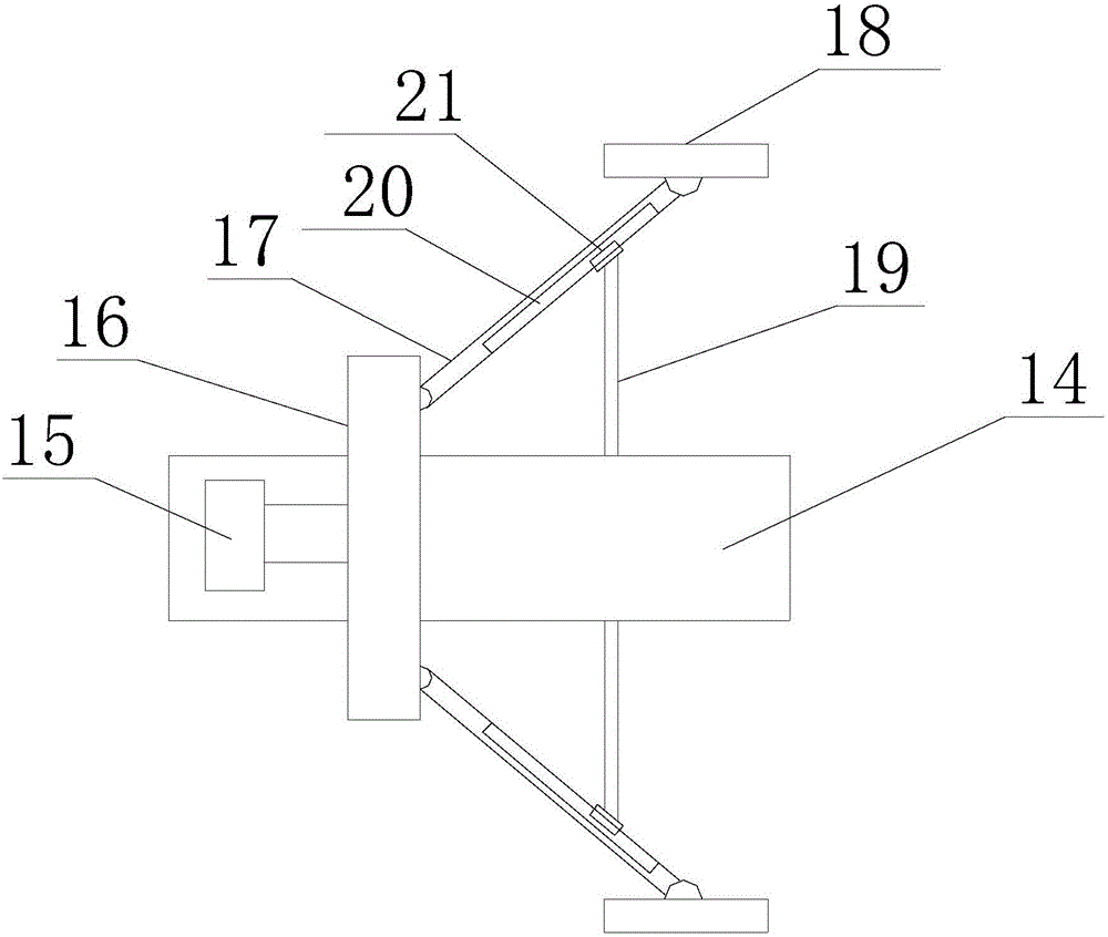
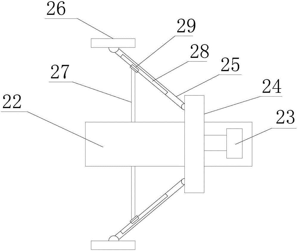
[0022] refer to figure 1 , figure 2 , image 3 , the present invention proposes a steel pipe multi-actuating mechanism synchronous drilling device, including a base 1, a first work frame 2, a second work frame 3, a first drive mechanism, a drilling mechanism and a support mechanism, wherein:

[0023] The base 1 is arranged horizontally, and the two ends of the base 1 are vertically provided with a first side frame 4 and a second side frame 5 arranged oppositely.

[0024] The first work frame 2 is located above the base 1 and is parallel to the base 1. The two ends of the first work frame 2 are respectively installed on the first side frame 4 and the second side frame 5. The first work frame 2 is arranged side by side along the horizontal direction A plurality of guide holes 6 run through the upper and lower surfaces of the guide hole 6 , and a guide sleeve set on the drill rod 7 is arranged in the guide hole 6 .

[0025] The second work frame 3 is located on the first work...


PUM


Abstract

The invention provides a synchronous steel pipe drilling device with multiple actuating mechanisms. The synchronous steel pipe drilling device comprises a base, a first working frame, a second working frame, a first driving mechanism, a drilling mechanism and a supporting mechanism, wherein two ends of the base are vertically provided with a first side frame and a second side frame which are oppositely arranged; two ends of the first working frame are respectively arranged on the first side frame and the second side frame; two ends of the second working frame are respectively and movably arranged on the first side frame and the second side frame; the first driving mechanism is connected with the second working frame and drives the second working frame to vertically move in the vertical direction; the drilling mechanism comprises a plurality of vertically arranged drilling rods and a plurality of drilling assemblies; and the supporting mechanism comprises a second driving mechanism, a first upright post and a second upright post, wherein the first upright post and the second upright post are arranged oppositely, the opposite surfaces of the first upright post and the second upright post are respectively provided with a first supporting assembly and a second supporting assembly, and the second driving mechanism is connected with the first supporting assembly and the second supporting assembly and drives the first supporting assembly and the second supporting assembly to rotate. The synchronous steel pipe drilling device is accurate in location, free of deflection and high in precision.

Description

technical field [0001] The invention relates to the technical field of mechanical processing equipment, in particular to a synchronous drilling device with multiple actuators for steel pipes. Background technique [0002] The traditional drilling method is pole drilling, which has the disadvantages of cumbersome procedures, low dimensional accuracy, low processing efficiency, and prone to distortion, which directly affects the smooth progress of subsequent processes. Of course, drilling machines can also be used to drill holes in steel pipes. However, traditional drilling machines need to mark the parts of the steel pipes to be drilled in advance, and the accuracy of steel pipe drilling depends largely on the position accuracy of the parts to be drilled. , and once the drilling is finished, if the drilling is required, the drilling operation needs to be stopped, and the position of the steel pipe to be drilled is marked again, which is time-consuming and laborious. Content...

Claims


Application Information

Patent Timeline
Patent Type & Authority Applications(China)
IPC IPC(8): B23B39/16B23B47/26B23B47/20B23B47/06B23B49/02B23Q3/06B23Q7/00B23Q11/00
CPCB23B39/161B23B47/26B23B49/02B23Q3/064B23Q5/10B23Q5/28B23Q7/00B23Q11/00
Inventor 山奎生
Owner ANHUI QIFENG MACHINERY & EQUIP
Learn More