
Milling clamp for plane of sliding saddle

A plane milling and fixture technology, applied in the direction of clamping, manufacturing tools, supports, etc., can solve the problems of workpiece movement, fixed support rods that are difficult to adjust, easy to loosen, etc.

Inactive Publication Date: 2016-07-06
ANHUI CHIZHOU HOUSEHOLD MACHINE TOOL
View PDF0 Cites 8 Cited by
  • Summary
  • Abstract
  • Description
  • Claims
  • Application Information

AI Technical Summary

Problems solved by technology

[0003] The purpose of the present invention is to overcome the defects of the prior art that when milling a large workpiece plane, the fixed support rod adopted by the traditional fixture is not easy to adjust, the workpiece is not stable in clamping, easy to loosen, unreliable in clamping, and easily causes the workpiece to move during processing. Design a sliding saddle plane milling fixture, which is simple to manufacture and easy to use. It adopts a combination of fixed support and floating support to prevent compression deformation and ensure machining accuracy. After the pressing plate is pressed against the workpiece, it is not easy to loosen and clamp. Reliable, easy to adjust the position of the pressure plate

Method used


Image

  • Milling clamp for plane of sliding saddle
  • Milling clamp for plane of sliding saddle
  • Milling clamp for plane of sliding saddle

Examples


Embodiment Construction

[0016] In order to make the technical means, creative features, goals and effects achieved by the present invention easy to understand, the present invention will be further described below in conjunction with specific illustrations.

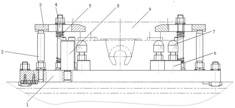
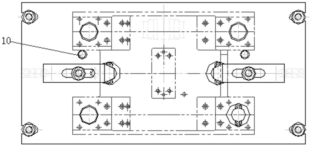
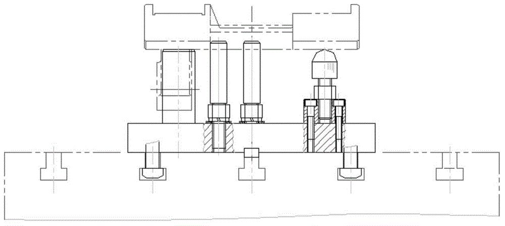
[0017] A saddle plane milling fixture, comprising a bottom plate 1, a pressure plate support rod 2, a pressure plate 3, a stud 4, a compression spring 5, a movable support seat 6, a movable ball head support 7, a workpiece support rod 8, a workpiece 9, a positioning The pin 10 and the bottom plate 1 are arranged horizontally, the bottom of the pressure plate support rod 2 is threaded, screwed into the bottom plate 1, one on the left and right, the pressure plate 3 is fixed on the pressure plate support rod 2, and the pressure plate 3 is pressed by the double-ended stud 4 and the nut , The upper surface of the bottom plate 1 is provided with a workpiece support rod 8, and the workpiece 9 is placed on the workpiece support rod 8 and positioned by a...


PUM


Abstract

The invention discloses a milling clamp for a plane of a sliding saddle and belongs to the technical field of machine tool clamp design. The milling clamp comprises a bottom plate, pressing plate supporting rods, pressing plates, studs, compression springs, movable supporting seats, movable ball head supports, a workpiece supporting rod, a workpiece and locating pins. The bottom plate is horizontally arranged. The bottom of each pressing plate supporting rod is provided with a thread. The two pressing plate supporting rods are screwed in the bottom plate, wherein one of the pressing plate supporting rods is arranged on the left, and the other pressing plate supporting rod is arranged on the right. The pressing plates are fixed to the pressing plate supporting rods. The pressing plates are pressed through cooperation of the studs and nuts. The workpiece supporting rod is arranged on the upper surface of the bottom plate, and therefore the workpiece is placed on the workpiece supporting rod and is located through the locating pins. The designed milling clamp for the plane of the sliding saddle is easy to manufacture and convenient to use, and a machined part is large in shape; a manner of combining fixed supporting and floating supporting is adopted, so that pressing deformation can be prevented, and the machining precision is ensured; and rod portions of the studs are sleeved with the compression springs, so that after the pressing plates are used for pressing the workpiece, the workpiece is not likely to be loosened, clamping is reliable, and the positions of the pressing plates are adjusted conveniently.

Description

technical field [0001] The invention relates to the technical field of machine tool fixture design, in particular to a sliding saddle plane milling fixture. Background technique [0002] With the development of the machinery industry, the requirements for the shape of the parts vary widely. Different shapes of workpieces must be processed on the machine tool using different clamping methods. For example, when milling the plane of a large workpiece, the fixed support rod used by the traditional fixture is not easy to adjust. The top of the support rod is flat, the workpiece is not clamped stably, lacks elastic parts when clamping, it is easy to loosen, the clamping is unreliable, and the workpiece is likely to move during processing. Machining accuracy, reliable clamping fixtures for plane milling of large workpieces are necessary. Contents of the invention [0003] The purpose of the present invention is to overcome the defects of the prior art that when milling a large w...

Claims


Application Information

Patent Timeline
Patent Type & Authority Applications(China)
IPC IPC(8): B23Q3/06
Inventor 方忠秀
Owner ANHUI CHIZHOU HOUSEHOLD MACHINE TOOL
Learn More