A continuous punching mechanism

A punching and connecting rod technology, applied in metal processing, etc., can solve the problems of wasting motor energy, increasing punching time, reducing mechanism life, etc., and achieves the effects of improving production efficiency, reducing vibration and noise, and simple structure

Active Publication Date: 2017-09-05
LANGRUI PACKAGING TECH CANGZHOU CO LTD
View PDF6 Cites 0 Cited by
  • Summary
  • Abstract
  • Description
  • Claims
  • Application Information

AI Technical Summary

Problems solved by technology

Moreover, most punching mechanisms punch holes in the static state of the film. After the punching is completed, the film travels one end distance before the next punching.
From stationary to moving of the film, the traction mechanism of the film needs to be started and stopped repeatedly, which wastes the energy of the motor, reduces the service life of the mechanism, and increases the punching time
[0003] In addition, the traditional slewing mechanism cannot realize the slewing while keeping the working surface in one orientation. If the orientation needs to be maintained, a more complicated structure needs to be added

Method used


Image

  • A continuous punching mechanism
  • A continuous punching mechanism
  • A continuous punching mechanism

Examples


Embodiment 1

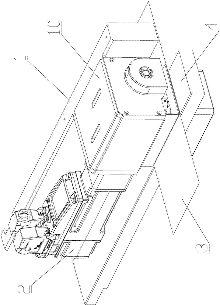
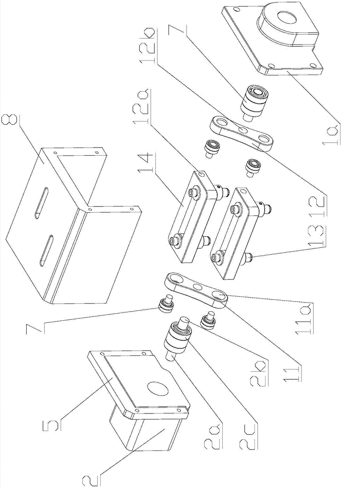
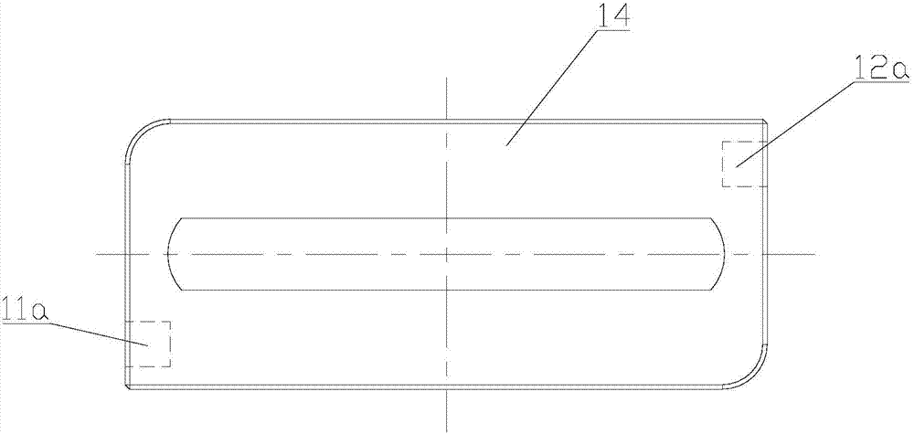
[0026] Such as Figure 1-3 As shown, a continuous punching mechanism provided in this embodiment includes a frame 1, a driving device 2 and two punching units 10; the punching unit 10 includes an inner connecting rod 11, an outer connecting rod 12, and a punch 13 and the punch installation seat plate 14; the power output shaft 2a of the driving device 2 is connected with one end of the inner connecting rod 11, and drives the inner connecting rod 11 to rotate; the other end of the inner connecting rod 11 is hingedly connected to the punch installation seat plate 14 On the inner side; one end of the outer connecting rod 12 is hinged on the support seat 1a on the frame 1, and the other end of the outer connecting rod 12 is hinged on the outer side of the punch mounting seat plate 14; the outer connecting rod 12 is connected to the inner side The connecting rods 11 have the same length and are parallel to each other; the hinge shaft axis of the outer connecting rod 12 and the fram...

Embodiment 2

[0034] This embodiment is basically the same as Embodiment 1, the difference is that, as Figure 4As shown, the continuous punching mechanism is simpler. This embodiment only includes one punching unit 10a, and the punching unit 10a includes an inner connecting rod 11a, an outer connecting rod 12a, a punch 13a and a punch mounting seat plate 14a. In the case of limited working space, the structure is simpler, easy to implement and popularize, and the mutual interference between multiple punching units is avoided.


PUM


Abstract

The invention relates to a continuous punching mechanism which comprises a rack, a driving device, inner connecting rods, outer connecting rods, punches and punch mounting seat plates. A power output shaft of the driving device is connected with one end of each inner connecting rod and drives the inner connecting rods to rotate; the other ends of the inner connecting rods are hinged to the inner side faces of the corresponding punch mounting seat plates. One end of each outer connecting rod is hinged to the rack, and the other end of each outer connecting rod is hinged to the outer side face of the corresponding punch mounting seat plate. The driving device drives the punch mounting seat plates to rotate up and down circularly through the inner connecting rods. The continuous punching mechanism is simple in structure, the punches continuously rotate in the same direction, a packaging bag film synchronously and horizontally moves, and punching is achieved in the moving process of the punches and the packaging bag film; the punching action is continuous without intermittence, so that production efficiency is improved; meanwhile, due to the fact that the reciprocating moving mode is not adopted as the moving mode of the punching mechanism any more, vibration and noise of overall equipment are effectively lowered, and higher-speed punching is possible.

Description

technical field [0001] The invention relates to the field of punching mechanisms, in particular to a continuous punching mechanism. Background technique [0002] The punching mechanism is widely used in bag making, packaging and occasions where holes need to be punched on films and plates. Most of the existing punching mechanisms punch holes through linear reciprocating motion between the punch head and the punch seat. During the reciprocating motion, especially when reaching the end of the stroke, a large acceleration will be generated when the direction of motion needs to be changed, which will have an impact on the overall equipment, resulting in vibration and noise, especially when the speed is high. Moreover, most punching mechanisms punch holes in a static state of the film. After punching, the film travels one end distance before punching the next time. From stationary to moving of the film, the traction mechanism of the film needs to be started and stopped repeated...

Claims


Application Information

Patent Timeline
Patent Type & Authority Patents(China)
IPC IPC(8): B26F1/08B26D5/18B26D7/06B26D5/22
CPCB26D5/18B26D5/22B26D7/06B26F1/08
Inventor 汪洪静刘瑞松
Owner LANGRUI PACKAGING TECH CANGZHOU CO LTD
Why Eureka
Try Eureka