Layout structure of slow cooling region for smelting slag

A technology of arranging structure and slow cooling zone, applied in the field of smelting, can solve the problems of economic burden, large floor space and high construction investment cost, and achieve the effect of reducing cooling cost, improving service life and avoiding frequent use.

Active Publication Date: 2016-07-06
铜陵有色金属集团股份有限公司
View PDF7 Cites 0 Cited by
  • Summary
  • Abstract
  • Description
  • Claims
  • Application Information

AI Technical Summary

Problems solved by technology

[0003] The technical defects of using the above technology to cool high-temperature smelting slag are as follows: first, copper mining enterprises need to arrange slag slow cooling area and slag heap area in the factory area at the same time, which occupies a large area and high construction investment cost; second, after statistical calculation, When the annual production of 400,000 tons of mineral cathode copper is produced, the annual output of slag of the flash smelting furnace is about 1.126 million tons. For this reason, about 360 slag bags need to be prepared to meet the needs of on-site production. The current market price of a slag bag is about 27 10,000 calculations, then 360 slag bags need to invest 97.2 million yuan. This shows that the investment cost of slag bags required by the existing slag cooling method is very high; third, in the slag cooling process of the prior art, due to the slag bag The high-temperature slag is loaded first, and then filled with a large amount of cold water to achieve the cooling of the slag, which makes the slag bag rapidly cooled and heated, and the alternation of hot and cold is too frequent. In actual operation, a large number of slag bags have slag leakage, and some have reached Unable to repair, the service life of the slag bag is low, which will undoubtedly cause economic burden to the enterprise

Method used


Image

  • Layout structure of slow cooling region for smelting slag
  • Layout structure of slow cooling region for smelting slag

Examples


Embodiment Construction

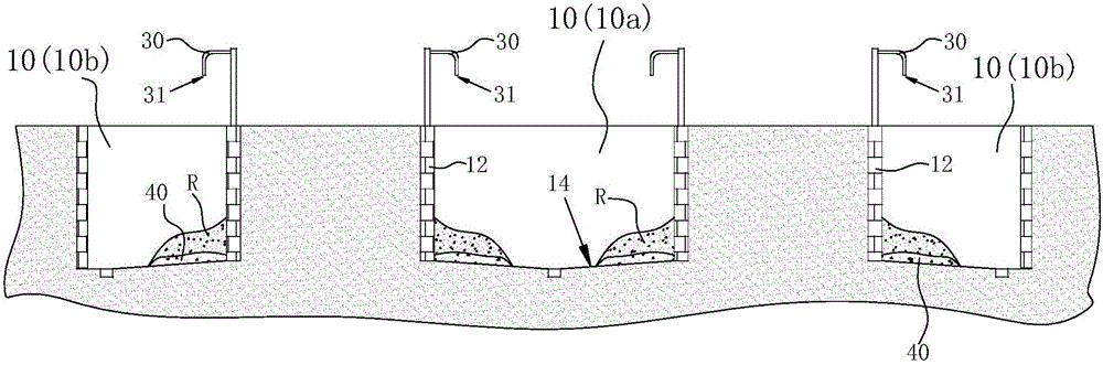
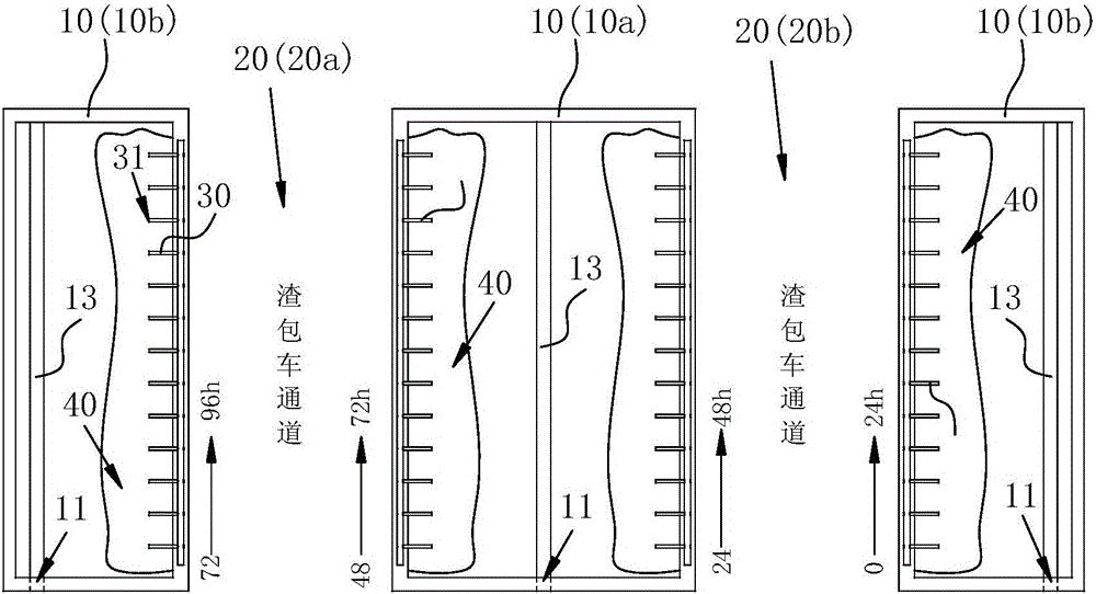
[0009] A layout structure of the slow cooling zone of smelting slag, such as Figure 1-2 As shown, it includes a slag-chartered vehicle channel 20, at least one side of the slag-chartered vehicle channel 20 is excavated with a slow cooling pool 10, and the slow cooling pool 10 is located on the edge of the pool on the side of the slag-chartered vehicle channel 20. Water pipes 30 are arranged at intervals, and the water pipes 30 The water inlet is connected to a water source, and the water outlet 31 of the water pipe 30 leads into the slow cooling pool 10 , and the bottom of the slow cooling pool 10 is provided with a drain port 11 . When in use, the slag-packed car transports the slag ladle loaded with hot smelting slag to the slow cooling zone, and reaches the side of the slow cooling pool 10 through the slag chartered car passage 20, and then pours the hot slag into the slow cooling pool 10, so that it flows into the slow cooling pool 10 through the water pipe 30 The heat ex...


PUM


Abstract

The invention discloses a layout structure of a slow cooling region for smelting slag. The layout structure comprises slag ladle vehicle passages; a slow cooling pool is dug in at least one side of each slag ladle vehicle passage; the pool side, located at the side where the corresponding slag ladle vehicle passage is located, of each slow cooling pool is provided with water pipes at intervals; water inlets of the water pipes are connected with a water source; water outlets of the water pipes are led into the slow cooling pools; and a drainage outlet is formed in the bottom of each slow cooling pool. When the layout structure is used, when a slag ladle vehicle carries slag ladles loaded with the hot smelting slag to arrive the pool sides of the slow cooling pools through each slag ladle vehicle passage, the hot smelting slag is directly poured into the slow cooling pools, and then, the hot smelting slag in the slow cooling pools can be cooled through heat exchange action of water; and after the hot smelting slag is cooled for a certain time, the cooled slag in the slow cooling pools is fished out by a forklift. Compared with the prior art, the layout structure disclosed by the invention has the advantages that the hot slag is directly poured into the slow cooling pools for cooling, and therefore not only is usage amount of the slag ladles reduced, but also the slag ladles are prevented from being frequently used in a quick cooling and heating state, and then, service lives of the slag ladles are greatly prolonged, and investment cost is greatly reduced.

Description

technical field [0001] The invention relates to the technical field of smelting, in particular to an arrangement structure of a slow cooling zone for smelting slag. Background technique [0002] In the prior art, the flash smelting furnace of copper ore is generally provided with 4 slag outlets. In actual production, there are usually 2-3 slag outlets to carry out slagging operations at the same time. The specific slag treatment method is: set the temperature The slag at 1280 ℃ ~ 1320 ℃ is first discharged to the slag bag through the slag chute of the slag outlet, and then transported to the slag slow cooling zone by the slag ladle car for slow cooling of the slag bag. The so-called slow cooling of the slag bag means passing through the slow cooling zone. The arranged water pipes continuously supply cold water to the slag bag to reduce the temperature of the slag bag and the slag in the slag bag. The hot water formed by heat exchange in the slag bag directly overflows from t...

Claims


Application Information

Patent Timeline
Patent Type & Authority Applications(China)
IPC IPC(8): C22B15/00
CPCC22B15/0047
Inventor 柴满林孟凡伟何桂荣
Owner 铜陵有色金属集团股份有限公司
Why Eureka
Try Eureka