
Device for hub detection

A detection device, hub technology, applied in measurement devices, material analysis using radiation, material analysis using wave/particle radiation, etc., can solve the problems of shortening the service life of X-ray tubes and imagers, shortage, power loss, etc., To achieve the effect of saving wheel hub loading and unloading time, improving use function and improving detection efficiency

Active Publication Date: 2016-07-06
苏州工业园区道青科技有限公司
View PDF6 Cites 4 Cited by
  • Summary
  • Abstract
  • Description
  • Claims
  • Application Information

AI Technical Summary

Problems solved by technology

However, sometimes it is necessary to select and adjust the X-ray imaging range and size according to the part of the wheel hub to be inspected to achieve more targeted detection and observation, and the current wheel hub inspection equipment lacks this function.
In addition, the wheel hub to be tested needs to be inspected in all directions, but the general wheel hub inspection equipment can only detect various parts of the wheel hub by adjusting the position of the X-ray tube and imager on the C-arm, which is very inconvenient and has many operational limitations Sexuality causes the hub to not be detected in all directions
In addition, the current wheel hub inspection equipment generally requires inspectors to manually transport the wheel hub to the stage, and then manually move it back after the inspection, which undoubtedly consumes a lot of workload and time. , it is necessary to turn off the X-ray tube and imager. Frequent switching of the X-ray tube and imager will cause power loss and shorten the service life of the X-ray tube and imager

Method used


Image

  • Device for hub detection
  • Device for hub detection
  • Device for hub detection

Examples


Embodiment Construction

[0026] The present invention will be further described in detail below in conjunction with the drawings.

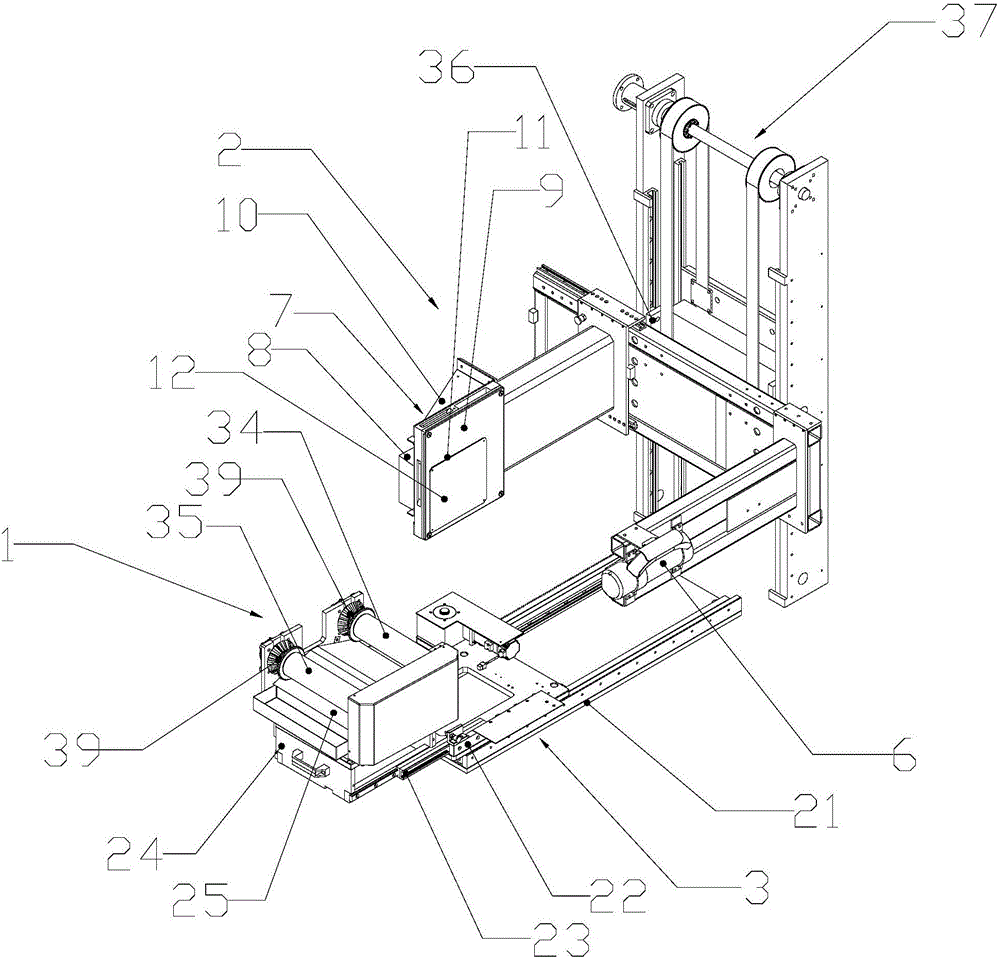
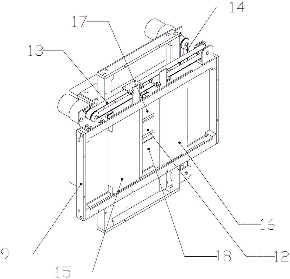
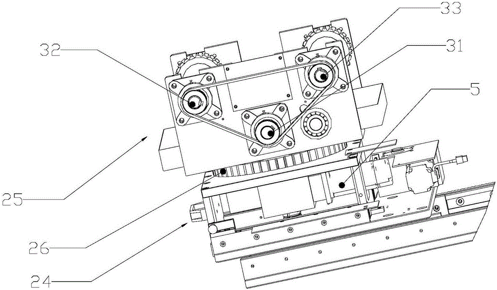
[0027] Figure 1 ~ Figure 4 A device for detecting a wheel hub according to an embodiment of the present invention is schematically shown. Such as Figure 1 ~ Figure 4 As shown, it includes a stage 1 and a detection device 2. The stage 1 is connected to the first transmission device 3 and the second transmission device respectively. The stage 1 can move horizontally under the action of the first transmission device 3, and the second transmission device The device is connected to the first driving device 5. The first driving device 5 drives the second transmission device so that the hub on the stage 1 can rotate in the horizontal and vertical directions at the same time; the detection device 2 includes an X-ray source 6, an imaging device 7, The X-ray source 6 and the imaging device 7 are located on both sides of the hub. The imaging device 7 includes a grating plate 9 and ...


PUM


Abstract

The invention discloses a device for hub detection.The device comprises an objective table and a detection device.The objective table is connected with a first transmission device and a second transmission device.The objective table can horizontally move under the effect of the first transmission device.The second transmission device is connected with a first driving device.The first driving device drives the second transmission device so that a hub on the objective table can rotate in both the horizontal direction and the perpendicular direction.The detection device comprises an X radiation source and an imaging device.The X radiation source and the imaging device are located on the two sides of the hub respectively.The imaging device comprises an optical grating plate and a detector.The surface of the optical grating plate is provided with an adjustable region defined by sliding stop pieces.The optical grating plate is connected with a second driving device.The second driving device can drive the optical grating plate to rotate perpendicularly.According to the device for hub detection, the automation degree and convenience of hub assembling and disassembling are improved, the comprehensive and non-dead-corner detection effect on the hub is achieved, and the using performance of the device for hub detection is enhanced.

Description

Technical field [0001] The present invention relates to the technical field of non-destructive testing equipment, in particular to a device for wheel hub testing. Background technique [0002] The current hub inspection equipment generally installs the X-ray tube and the imager on the two ends of the C-arm, and puts the hub on the stage, between the X-ray tube and the imager, and sends out through the X-ray tube. X-ray detection of the wheel hub, the imager presents the image on the display terminal. However, because sometimes it is necessary to select and adjust the X-ray imaging range and size according to the part to be inspected on the hub to achieve more targeted inspection and observation, the current hub inspection equipment lacks this function. In addition, the wheel to be inspected needs to be inspected in all directions, but the general wheel inspection equipment can only inspect various parts of the wheel by adjusting the position of the X-ray tube and the imager on t...

Claims


Application Information

Patent Timeline
IPC IPC(8): G01N23/00G01N23/04
CPCG01N23/00G01N23/04
Inventor 陶维道刘军张建宇刘强
Owner 苏州工业园区道青科技有限公司
Learn More