
Coupling plate assembly used for electrostatic discharge test and electrostatic discharge test device

An electrostatic discharge test and coupling board technology, applied in the direction of measuring devices, measuring external source interference, measuring electricity, etc., can solve the problems of low test efficiency, complicated test process, and inaccurate test results, so as to improve test efficiency, The effect of convenient operation and simple structure

Inactive Publication Date: 2016-07-06
WALTEK SERVICES SUZHOU
View PDF6 Cites 3 Cited by
  • Summary
  • Abstract
  • Description
  • Claims
  • Application Information

AI Technical Summary

Problems solved by technology

[0006] The object of the present invention is to propose a coupling plate assembly for electrostatic discharge testing. Through the coupling plate assembly composed of a plurality of coupling plates, a full range of vertical coupling discharge tests are carried out on the object to be tested, which solves the problem that the prior art only uses one The discharge test of the coupling board needs to move the object under test back and forth, resulting in inaccurate test results, complicated test process, and low test efficiency.

Method used


Image

  • Coupling plate assembly used for electrostatic discharge test and electrostatic discharge test device

Examples


Embodiment 1

[0025] In the electrostatic discharge test of the prior art, the test object is usually discharged by setting a coupling plate, because the test object has different surfaces, and when the vertical coupling discharge test is performed on the test object (EUT), it is necessary to continuously Move the EUT to test the surface to be tested. Especially when the shape of the EUT is irregular, it is difficult to conduct a full range of vertical coupling discharge tests on the EUT.

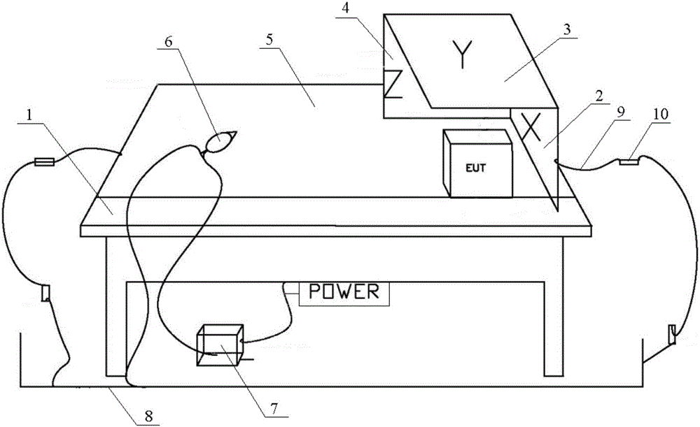
[0026] In view of the above problems, the present invention provides a coupling plate assembly for electrostatic discharge testing, such as figure 1 As shown, it includes: a horizontal coupling plate 5 laid on the test table 1, a first coupling plate 2 perpendicular to the test table 1, and a second coupling plate 3 vertically connected to the first coupling plate 1, the horizontal An insulating plate for placing the object to be measured is also arranged on the coupling plate 5 .

[0027] The second c...

Embodiment 2

[0036] Different from Embodiment 1, it also includes a fourth coupling plate parallel to the first coupling plate 2 and a fifth coupling plate perpendicular to the first coupling plate 2, the first coupling plate 2, the second coupling plate 3 , the third coupling plate 4 , the fourth coupling plate, the fifth coupling plate and the horizontal coupling plate 5 form a closed space for testing the antistatic ability of the object to be tested.

[0037] To sum up, through the coupling plate assembly composed of multiple coupling plates, a full range of vertical coupling discharge tests are performed on the object to be tested. The structure is simple and the operation is convenient, which not only improves the test efficiency, but also improves the accuracy of the test.


PUM


Abstract

The present invention relates to the antistatic test technology field, in particular to a coupling plate assembly used for an electrostatic discharge test and an electrostatic discharge test device. The coupling plate assembly used for the electrostatic discharge test comprises a horizontal coupling plate laid on a test table-board, a first coupling plate vertical with the test table-board and a second coupling plate connected with the first coupling plate vertically, and the horizontal coupling plate is also equipped with an insulating plate used for placing a to-be-tested object. The electrostatic discharge test device is equipped with the coupling plate assembly, the coupling plate assembly is connected with a detection circuit, and the detection circuit comprises coupling conducting wires connected with the coupling plate and an electrostatic gun connected with the coupling conducting wires. The electrostatic gun is connected with an electrostatic simulator, and at least one point of each coupling conducting wire is connected with a grounding flat plate. The coupling plate assembly used for the electrostatic discharge test and the electrostatic discharge test device can carry out the omnibearing vertical coupling discharge test on the to-be-tested object, are simple in structure, are convenient to operate, and enables the test efficiency and the test accuracy to be improved.

Description

technical field [0001] The invention relates to the technical field of antistatic testing, in particular to a coupling plate assembly and an electrostatic discharge testing device for electrostatic discharge testing. Background technique [0002] Electrostatic discharge test is divided into direct discharge and indirect discharge two discharge methods. Among them, the direct discharge is the discharge to the equipment under test, and the indirect discharge is the discharge to the coupling plate. [0003] The direct discharge to the equipment under test is divided into contact discharge and non-contact discharge (air discharge) according to the different discharge methods. The method of contact discharge is to contact the tip of the discharge gun with the test point, and then turn on the switch in the discharge gun. The method of non-contact discharge is that after turning on the discharge switch, the discharge end of the discharge gun is gradually approached to the equipme...

Claims


Application Information

Patent Timeline
IPC IPC(8): G01R31/00
CPCG01R31/001
Inventor 张海清郁程
Owner WALTEK SERVICES SUZHOU
Learn More