Tester for secondary polarity test of remotely-controllable mutual inductor

A secondary polarity and polarity testing technology, which is applied in the direction of electrical winding testing, instrumentation, and electrical measurement, can solve problems such as low efficiency, wrong test conclusions, hidden dangers in safe operation of equipment, etc., to shorten test time and simplify Experimental process, the effect of improving work efficiency

Inactive Publication Date: 2016-07-06
ZAOZHUANG POWER SUPPLY COMPANY OF STATE GRID SHANDONG ELECTRIC POWER +1
View PDF7 Cites 1 Cited by
  • Summary
  • Abstract
  • Description
  • Claims
  • Application Information

AI Technical Summary

Problems solved by technology

(One-time test) The amount of test power supply is artificially controlled, and there are often irregular contact and disconnection times, and the outdoor test operation and indoor test observation are not synchronized, resulting in unclear test results and repeated tests. Too many times will easily lead to a decrease in the continuous discharge capacity of the power supply battery and affect the test work
The polarity test is usually tested phase by phase. The transformer has three phases and each phase (secondary side) has multiple windings. The tester needs to change the phase outdoors multiple times and frequently transfer and change the test location (different secondary acquisition terminal screens) ), so the polarity test is passive and inefficient. Sometimes the above reasons cause repetitive work, and even wrong test conclusions, which bury hidden dangers for the safe operation of the equipment

Method used


Image

  • Tester for secondary polarity test of remotely-controllable mutual inductor
  • Tester for secondary polarity test of remotely-controllable mutual inductor
  • Tester for secondary polarity test of remotely-controllable mutual inductor

Examples


Embodiment Construction

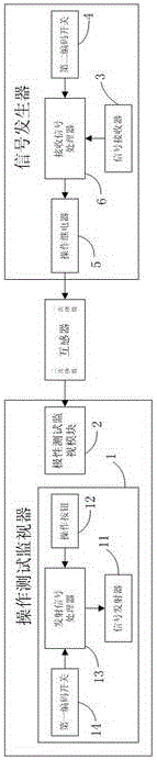
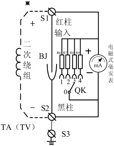
[0027] exist figure 1 A schematic diagram of a remote-controlled transformer secondary polarity tester is shown in . Such as figure 1 As shown, a remote-controlled transformer secondary polarity test tester includes: a signal generator and an operation test monitor. The signal generator is electrically connected with the primary winding of the transformer, and is used for applying instantaneous voltage at the primary winding of the transformer. The operation test monitor includes a remote command module 1 and a polarity test monitoring module 2. The remote command module 1 is used to wirelessly control the signal generator to apply an instantaneous voltage at the primary winding of the transformer. The polarity test monitoring module 2 and the transformer two The secondary winding is electrically connected to measure the current generated at the secondary winding of the transformer.

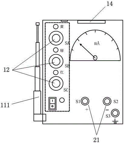
[0028] The remote control command module 1 includes: a signal transmitter 11, which is use...


PUM


Abstract

The invention discloses a tester for a secondary polarity test of a remotely-controllable mutual inductor. The tester comprises an operation test monitor and a signal generator. The signal generator is in electrical connection with a primary winding of the mutual inductor and is used for applying an instantaneous voltage to the primary winding of the mutual inductor. The operation test monitor comprises a remote control instruction module and a polarity test monitoring module. The remote control instruction module is used for emitting an instruction to the signal generator in a wireless mode so as to control the signal generator to apply the instantaneous voltage to the primary winding of the mutual inductor. The polarity test monitoring module is in electrical connection with a secondary winding of the mutual inductor and is used for measuring a current generated at the secondary winding of the mutual inductor. According to the invention, the tester for the secondary polarity test of the remotely-controllable mutual inductor is mainly used for measuring the secondary polarity of the mutual inductor, original two groups of test personnel are reduced to one group by adding a remote control function, the manpower and material resources are saved, the using is convenient, the efficiency is high, and the performance is reliable.

Description

technical field [0001] The invention relates to the technical field of transformer secondary polarity test, in particular to a remote-controllable transformer secondary polarity test tester. Background technique [0002] Polarity test is an effective simulation verification that must be carried out after the new installation, modification or change of wiring of transformers and other equipment in the field of relay protection and electrical test of power system. It is one of the important tasks of this major. Passing the polarity test It can detect possible problems in the internal and external wiring of transformer (primary and secondary) winding coils and circuits in advance, verify the correctness of equipment and circuit wiring, and ensure the safe operation of electrical equipment. The current polarity test equipment can no longer meet the requirements of high efficiency. Requirements, only continuous innovation can solve the problem of many field test personnel and low...

Claims


Application Information

Patent Timeline
IPC IPC(8): G01R31/06
CPCG01R31/72
Inventor 李铁夫徐勤超张松仲浩张萍张旭袁震方保垒李业锋贾寅飞吕妍刘玉娇张琪王淦王任邱文马伟袁强秦贺胡凡孟凡波田家铭宋哲君刘旭阳李文利薛冰郝琨刘世林全先树
Owner ZAOZHUANG POWER SUPPLY COMPANY OF STATE GRID SHANDONG ELECTRIC POWER
Why Eureka
Try Eureka