Method and circuit for forming pulse flow in ultrasonic signal sparse sampling

A sparse sampling, ultrasonic signal technology, applied in the direction of radio wave measurement systems, instruments, etc.

Active Publication Date: 2016-07-06
JIANGSU UNIV
View PDF2 Cites 12 Cited by
  • Summary
  • Abstract
  • Description
  • Claims
  • Application Information

AI Technical Summary

Problems solved by technology

[0006] In order to solve the problem that the existing software algorithm cannot realize the direct physical sampling of ultrasonic signal FRI, the present invention proposes a physical formation method and circuit of ultrasonic pulse flow based on the principle of orthogonal demodulation, and uses analog circuits to realize the direct extraction of pulse flow from ultrasonic signals Signal

Method used


Image

  • Method and circuit for forming pulse flow in ultrasonic signal sparse sampling
  • Method and circuit for forming pulse flow in ultrasonic signal sparse sampling
  • Method and circuit for forming pulse flow in ultrasonic signal sparse sampling

Examples


Embodiment Construction

[0048] The technical solutions of the present invention will be further described below in conjunction with the accompanying drawings and embodiments.

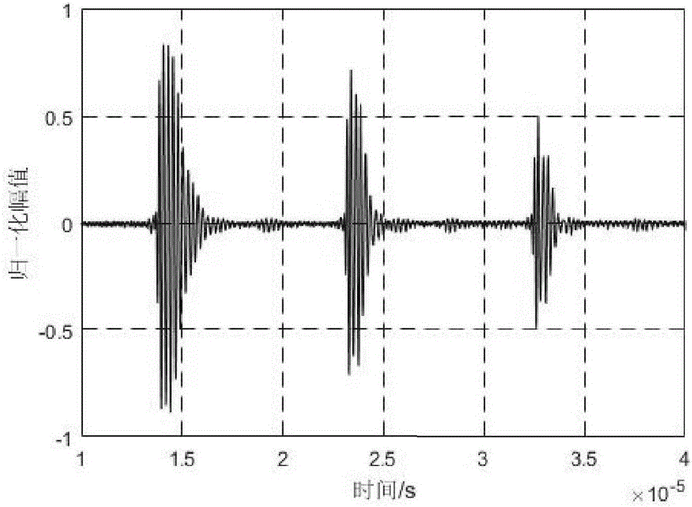
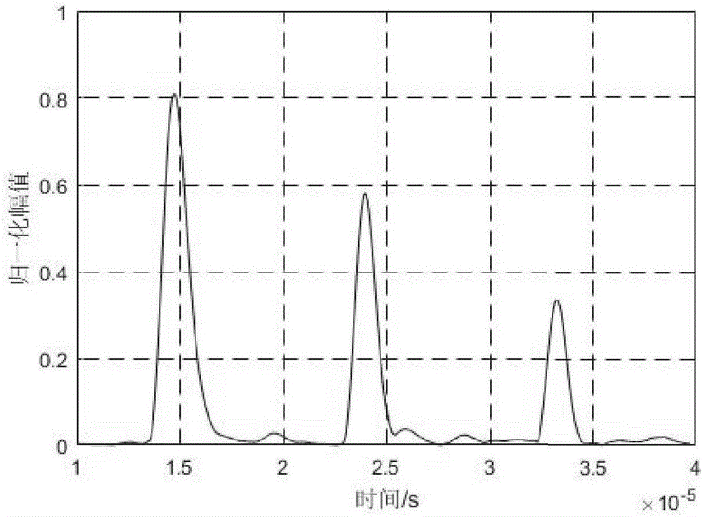
[0049] The actual ultrasonic echo signal used in this embodiment is as follows figure 2 shown. The center frequency of the ultrasonic probe is 5MHz, and the center frequency f of the echo signal is actually measured 0 About 3.5MHz.

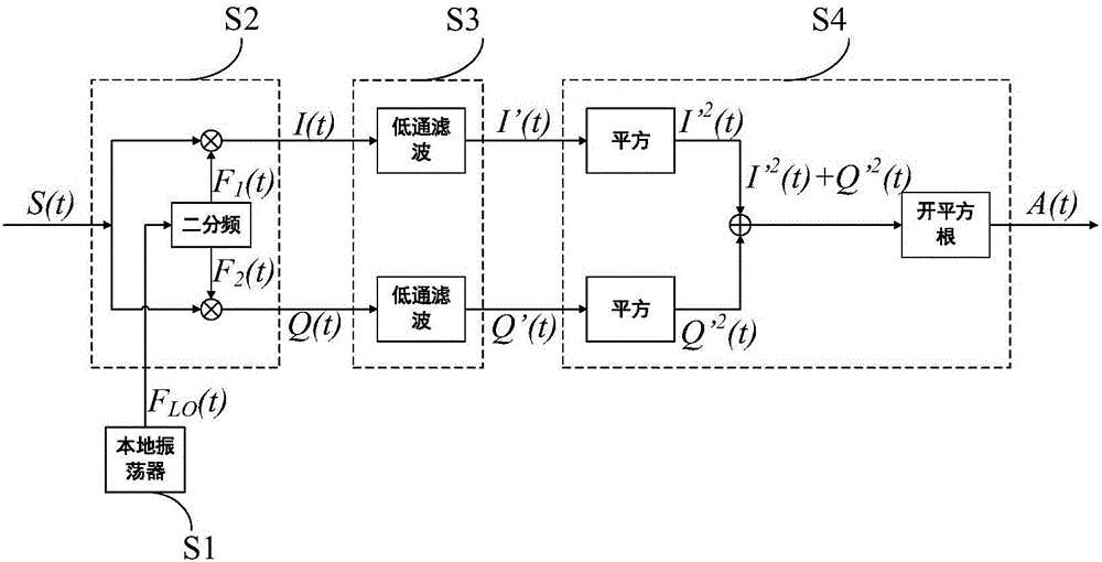
[0050] Determine the oscillation output signal F of the local oscillator according to the center frequency of the actual echo signal LO (t) frequency f c :

[0051] f c = 2f 0 =7MHz

[0052] Due to the actual ultrasonic echo signal center frequency f 0 Affected by external factors, there will be a certain frequency fluctuation, and the oscillation signal F LO (t) Due to the performance limitation of the analog circuit, there will also be a certain frequency deviation between the calculated value and the theoretical value. Therefore, there is a certain frequency difference Δf between the...


PUM


Abstract

The invention discloses a method and a circuit for forming a pulse flow in the ultrasonic signal sparse sampling. The method includes the steps that: S1, a local oscillator generates an oscillating signal having the oscillating frequency two times of the center frequency of an ultrasonic signal S(t); S2, two divided-frequency is carried out on the oscillating signal, so that two paths of square signals are generated, and the two paths of square signals and the S(t) are independently modulated and mixed; S3, the two paths of modulated and mixing signals pass a low pass filter, and two paths of output signals are generated; S4, the square operation is respectively carried out on the two paths of output signals of the S3, square values are added, and then a square root value of an addition value is obtained, and a final output signal A(t) which is the pulse flow obtained by detecting the ultrasonic signal S(t) is obtained. A circuit function module comprises a local oscillation module, an orthogonal frequency mixing module, a low pass filtering module and a modular arithmetic module. The method and the circuit for forming the pulse flow in the ultrasonic signal sparse sampling are especially suitable for realizing the sparse sampling at a low speed in the ultrasonic signal sparse sampling system based on a limited rate of innovation. The speed of the sparse sampling is greatly lower than a conventional Nyquist sampling speed. On the basis of maintenance of original signal information, the problem of a large data amount of a conventional sampling method is solved, and the ultrasonic pulse flow can be formed in real time.

Description

technical field [0001] The invention belongs to the technical field of sparse sampling of ultrasonic signals, and in particular relates to a method for forming a pulse flow in sparse sampling of ultrasonic signals based on a limited innovation rate and a hardware front-end physical realization circuit. Background technique [0002] Ultrasonic testing is an important non-destructive testing method. In order to improve the detection efficiency, improve the detection rate and imaging resolution of internal defects of materials, multi-sensor array structure, high detection frequency, and long-term detection are often used. Obtain rich ultrasonic echo information of the target body. However, the unfavorable consequence is that there is a large amount of detection data, which brings great difficulties to the collection, transmission, storage and real-time processing of signals. In order to solve this problem, researchers have explored new data sampling methods other than the conv...

Claims


Application Information

Patent Timeline
Patent Type & Authority Applications(China)
IPC IPC(8): G01S7/483G01S7/52
CPCG01S7/483G01S7/52G01S7/52036
Inventor 宋寿鹏江洲胥保文路欣潘海彬鲍丙好
Owner JIANGSU UNIV
Why Eureka
Try Eureka