Chassis temperature control system

A temperature control system and chassis technology, applied in the computer field, can solve the problems of controlling the fan speed, overheating of the main board, failure to reach, etc., to achieve the effect of reducing accumulation, realizing precise control, and prolonging the service life

Inactive Publication Date: 2016-07-06
LUOYANG INST OF SCI & TECH
View PDF6 Cites 6 Cited by
  • Summary
  • Abstract
  • Description
  • Claims
  • Application Information

AI Technical Summary

Problems solved by technology

[0002] The temperature control of traditional chassis such as computer chassis usually directly uses the power supply to supply power to the fan, and the fan rotates constantly to control the temperature of the chassis, which not only makes it difficult to accurately control the temperature of the chassis, but also causes a large waste of electric energy
Sometimes in the prior art, in order to reduce noise, an adjustable rheostat is also used to adjust the fan speed, but this artificial adjustment does not control the fan speed according to the actual temperature of the chassis, and cannot control the temperature in the chassis to a minimum level according to the actual environment. within the ideal range
In the prior art, there is also a technology that detects the temperature in the chassis by installing a temperature sensor in the chassis, and controls

Method used


Image

  • Chassis temperature control system
  • Chassis temperature control system
  • Chassis temperature control system

Examples


Embodiment Construction

[0021] In order to make the objects and advantages of the present invention clearer, the present invention will be further described in detail below in conjunction with the examples. It should be understood that the specific embodiments described here are only used to explain the present invention, not to limit the present invention.

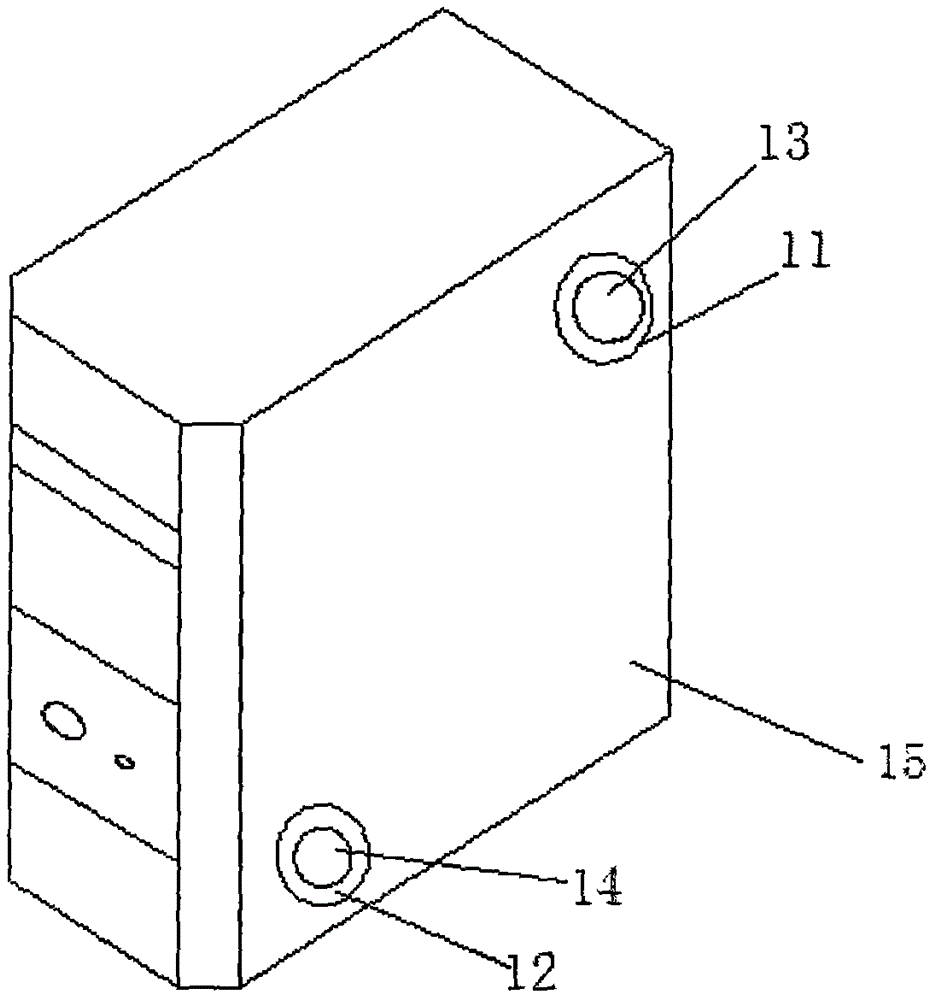
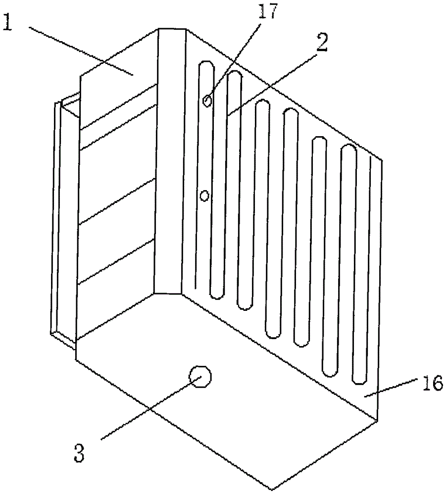
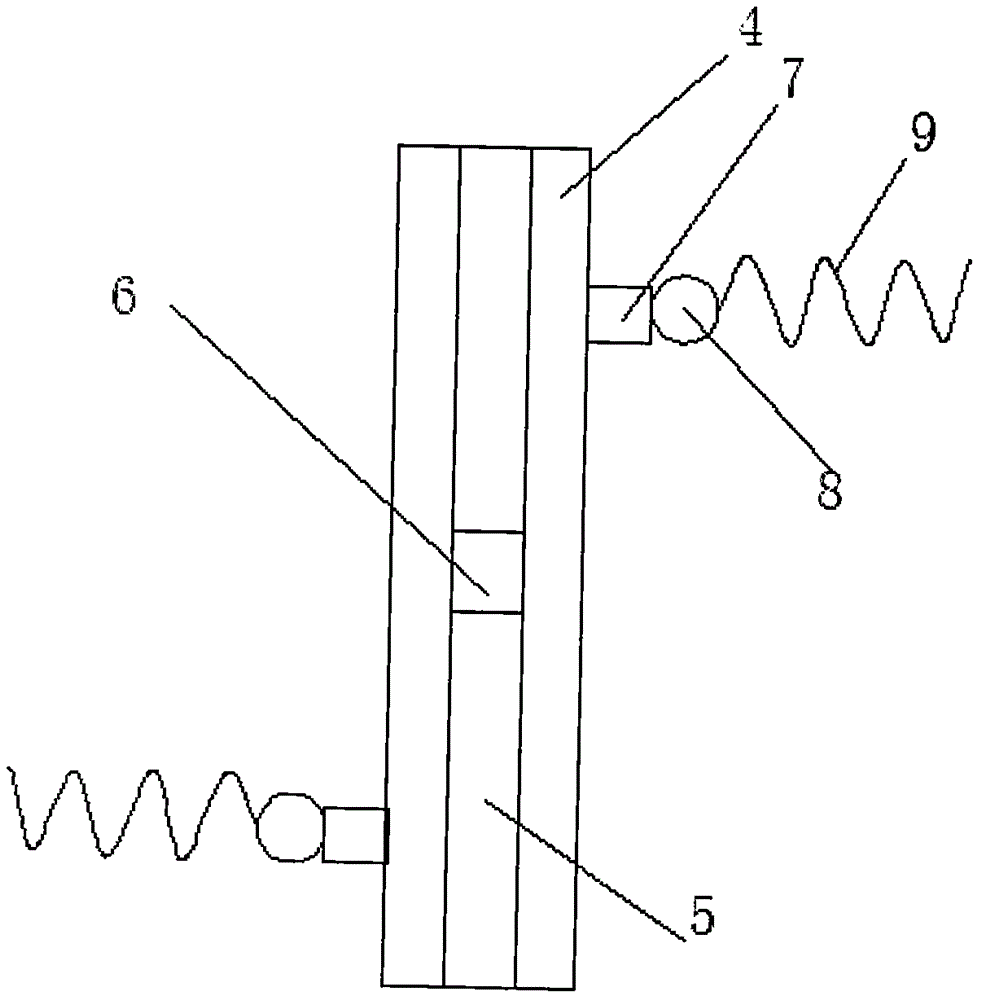
[0022] Such as Figure 1-5 As shown, the embodiment of the present invention provides a chassis temperature control system, including a chassis body 1 and a movable plate 10 slidingly connected to the chassis 1, and a motherboard mounting plate 18 is installed on the inner side wall 16 of the chassis body 1 through a spring mounting member 17 A cooling coil layer 2 is installed between the main board mounting plate 18 and the inner side wall 16, the cooling coil layer 2 is installed on the inner side wall 16 through a mounting piece, and the water inlet end of the cooling coil layer 2 is connected with a low-temperature water cooling circulation...


PUM


Abstract

The present invention discloses a chassis temperature control system. The chassis temperature control system is characterized in that a mainboard installation plate is installed on the inner side wall of a chassis body via a spring installing member, a cooling coil layer is installed between the mainboard installation plate and the inner side wall and is installed on the inner side wall via an installing member; an installing rod is arranged inside the classis body, the front, back, left and right sides of the installing rod are all equipped with the chutes, and each chute is connected with a motor via a sliding block with a servo device; the rotating shaft end of the motor is connected with an air cooler, and the air-out end of the air cooler is in threaded connection with a spiral coil; a movable plate is equipped with an air outlet and an air inlet, and the air outlet and the air inlet are in the diagonal arrangement; a first dust filtering fan is arranged in the air outlet, and a second dust filtering fan is arranged in the air inlet. According to the present invention, the temperature sensors are in the stagger installation, the concrete positions of the temperature sensors on the chassis are obtained while the temperature is detected, and then a refrigerating plant operates via a single-chip microcomputer, thereby realizing the accurate control of the chassis internal temperature.

Description

technical field [0001] The invention relates to the computer field, in particular to a case temperature control system. Background technique [0002] The temperature control of traditional chassis such as computer chassis generally uses the power supply to supply power to the fan, and the fan rotates constantly to control the temperature of the chassis. This is not only difficult to achieve accurate control of the temperature of the chassis, but also causes a large waste of electric energy. Sometimes in the prior art, in order to reduce noise, an adjustable rheostat is also used to adjust the fan speed, but this artificial adjustment does not control the fan speed according to the actual temperature of the chassis, and cannot control the temperature in the chassis to a minimum level according to the actual environment. within the ideal range. In the prior art, there is also a technology that detects the temperature in the chassis by installing a temperature sensor in the ch...

Claims


Application Information

Patent Timeline
IPC IPC(8): G05D23/20G06F1/20
CPCG05D23/20G06F1/20
Inventor 张果赵艳花
Owner LUOYANG INST OF SCI & TECH
Why Eureka
Try Eureka