
Wind vibration simulation method of 220kV power transmission line tower line coupled system

A technology of transmission line tower and simulation method, which is applied in design optimization/simulation, system integration technology, electrical digital data processing, etc., and can solve problems such as complex form-finding process, time-consuming, and neglect of structural damping

Inactive Publication Date: 2016-07-06
XI AN JIAOTONG UNIV +2
View PDF2 Cites 25 Cited by
  • Summary
  • Abstract
  • Description
  • Claims
  • Application Information

AI Technical Summary

Problems solved by technology

However, there are still the following deficiencies: 1. In order to reduce corona loss and increase transmission capacity, the transmission lines of 220kV and above voltage levels in my country use split conductors
Some studies have considered the form-finding of the tower-line coupling system, but the form-finding process is complicated and time-consuming
In Chinese Patent Publication No. CN103455686A "Modeling Method for Finite Element Model of Overhead Transmission Tower-Line Coupling System", the modeling of the ground wire adopts a straight line to connect the hanging point of the insulator and divide it into wire units of 0.9-1.1m. Here On the basis of multiple self-weight analysis of the tower-line coupling system to obtain an accurate transmission line tower-line coupling system, this method has many iterations and takes a long time to find the form
3. The structural damping effect is ignored in the wind vibration analysis of the transmission line tower line coupling system

Method used


Image

  • Wind vibration simulation method of 220kV power transmission line tower line coupled system
  • Wind vibration simulation method of 220kV power transmission line tower line coupled system
  • Wind vibration simulation method of 220kV power transmission line tower line coupled system

Examples


Embodiment Construction

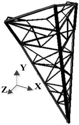
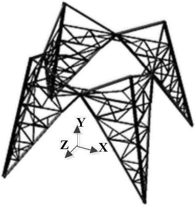
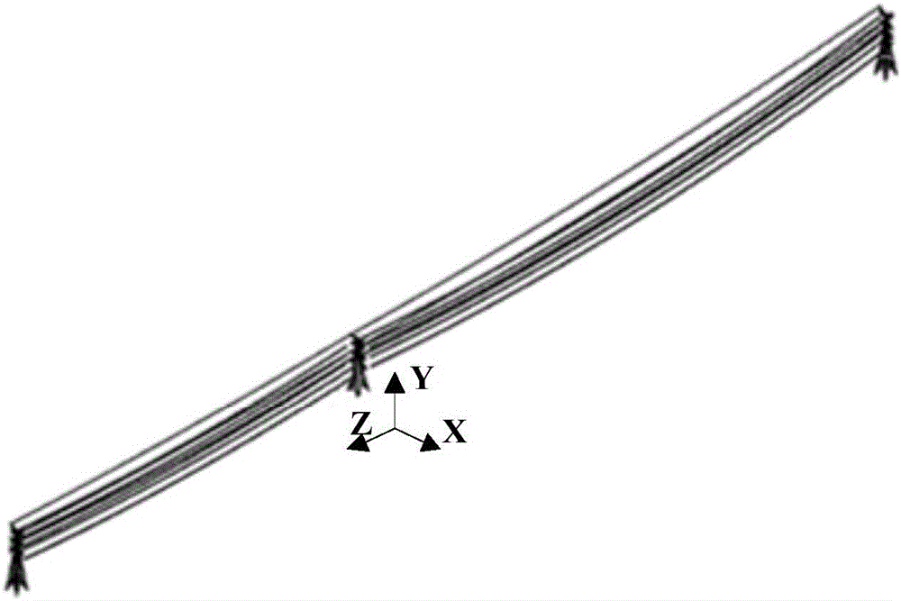
[0044] see Figure 1 to Figure 9 As shown, a kind of 220kV transmission line tower line coupling system wind vibration simulation method of the present invention comprises the following steps:

[0045] Step 1: Establish a finite element model of the transmission line tower-line coupling system;

[0046] Step 1-1: Modeling the transmission tower

[0047] Use the APDL language of ANSYS software to model the transmission tower, make full use of the high symmetry of the transmission tower, use the unit mirroring command to model the tower for the symmetrical part of the tower, and merge the redundant nodes and units after the mirror unit to form the tower Model.

[0048] Step 1-2: Modeling of insulators and split conductor spacers

[0049] Steps 1-3: Split sub-wire and ground wire modeling

[0050]The shape formed by the transmission line in the natural suspension state is a catenary line. Meng Suimin et al. gave the catenary line equation of the overhead wire:

[0051] ...


PUM


Abstract

The invention discloses a wind vibration simulation method of a 220kV power transmission line tower line coupled system. The wind vibration simulation method comprises the following steps: 1: establishing a finite element model of the power transmission line tower line coupled system; 2: carrying out formfinding on the power transmission line tower line coupled system; 3: carrying out wind load calculation on the power transmission line tower line coupled system; 4: carrying out damping calculation on the power transmission line tower line coupled system; and 5: carrying out wind vibration response calculation and data extraction analysis. The wind vibration simulation method establishes a fine and accurate finite element model of the power transmission line tower line coupled system, and considers the influence of structural damping during wind vibration simulation calculation. The wind vibration simulation method is suitable for carrying out wind vibration analysis on a power transmission line of an area where wind damage frequently happens. On the basis, the power transmission line is subjected to local reinforcement and wind damage early warning to minimize the disaster loss.

Description

technical field [0001] The invention relates to a wind vibration simulation method for a tower-wire coupling system of a 220kV transmission line. Background technique [0002] Transmission lines are mainly composed of transmission towers, conductors, overhead ground wires, insulators (strings), line fittings and grounding devices. Transmission lines are large-span, high-flexible structures that are extremely sensitive to wind loads. Under the action of strong wind, the line and the tower will vibrate to a large extent, and the line and the tower will affect each other through vibration to form a complex dynamic coupling system. At the beginning of the design of the overhead transmission line, the design of the wire and the tower structure is usually carried out separately. The method of quasi-static analysis is used to multiply the wind load on the ground wire by the wind vibration coefficient as a static load and apply it to the transmission tower hanger. On the point of ...

Claims


Application Information

Patent Timeline
Patent Type & Authority Applications(China)
IPC IPC(8): G06F17/50G06Q50/06
CPCG06Q50/06G06F30/23Y02E40/70Y04S10/50
Inventor 贺博厉天威豆敏娜罗兵修娅萍刘磊王雨李敏李斌唐力
Owner XI AN JIAOTONG UNIV
Learn More