An output overcurrent protection circuit composed of a reference source and a resistor

A reference source and resistance technology, applied in the circuit field, can solve the problems of high cost and complex circuit, and achieve the effect of reliable overcurrent protection, simple circuit structure and cost reduction

CN105743059BActive Publication Date: 2018-10-23SUZHOU R&D CENT OF NO 214 RES INST OF CHINA NORTH IND GRP
5 Cites 0 Cited by

Patent Information

Authority / Receiving Office
CN · China
Patent Type
Patents(China)
Current Assignee / Owner
Publication Date
2018-10-23

Smart Images

  • Figure 1
    Figure 1
  • Figure 2
    Figure 2
Patent Text Reader

Abstract

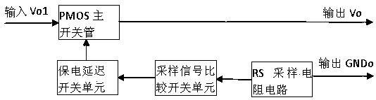
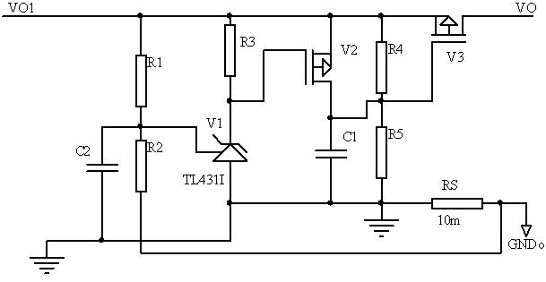
The invention discloses an output over-current protection circuit formed by a reference source and a resistor. The output over-current protection circuit comprises a sampling resistor, a sampling signal comparison switch unit, an electricity-maintaining delay switch unit and a PMOS main switch tube, wherein the sampling signal comparison switch unit judges the relationship between a sampling voltage and a reference threshold voltage according to the sampling voltage of the sampling resistor; when the sampling voltage is not smaller than the reference threshold voltage, the electricity-maintaining delay switch unit is charged, the PMOS main switch tube is closed, an input voltage is disconnected from an output voltage and the input voltage is a to-be-protected voltage of a power output end; and when the sampling voltage is smaller than the reference threshold voltage, the electricity-maintaining delay switch unit is discharged, the PMOS main switch tube is started after a delay of discharge time and the output voltage is normal. The output over-current protection circuit disclosed by the invention only adopts the components of the sampling resistor, the reference source, a PMOS tube and the like, so that the circuit is simple in structure, utilization of an operational amplifier is avoided and the cost is greatly reduced; and the over-current protection is reliable.
Need to check novelty before this filing date? Find Prior Art

Description

technical field

[0001] The invention relates to an overcurrent protection circuit, which belongs to the technical field of circuits. Background technique

[0002] The overcurrent protection circuit at the power output end is generally composed of a sampling resistor, an operational amplifier, a reference source, and a control switch. Since this solution includes an operational amplifier, the cost of the circuit is relatively high. There are also some overcurrent protection circuits that use control integrated circuit chips, which makes the circuit very complicated and the cost is also high. Contents of the invention

[0003] The technical problem to be solved by the present invention is to provide an output overcurrent protection circuit composed of a reference source and a resistor, the circuit structure is simple, the cost is low, and the overcurrent protection is reliable.

[0004] In order to solve the above-mentioned technical problems, the present invention provides...

Examples

Embodiment Construction

[0015] The present invention will be further described below in conjunction with the accompanying drawings. The following examples are only used to illustrate the technical solution of the present invention more clearly, but not to limit the protection scope of the present invention.

[0016] Such as figure 1 and figure 2 shown. The invention is mainly composed of an RS sampling resistance circuit, a sampling signal comparison switch unit, a battery delay switch unit and a PMOS main switch tube. The sampling signal comparison switching unit judges the relationship between the voltage and the reference threshold voltage according to the voltage of the RS sampling resistance circuit. Turn on the output voltage; when the sampling voltage is lower than the reference threshold voltage, the power protection delays the discharge of the switch unit, so that the PMOS main switch V3 is turned on after a discharge time delay, so that the output voltage is normal.

[0017] The RS sam...