Resonance compensation method for wireless power transmission system with random constant-current output

A technology of wireless power transmission and compensation method, applied in the direction of electrical components, circuit devices, etc., can solve the problems of reducing system design flexibility and economy

Inactive Publication Date: 2016-07-06
FUZHOU UNIV
View PDF4 Cites 1 Cited by
  • Summary
  • Abstract
  • Description
  • Claims
  • Application Information

AI Technical Summary

Problems solved by technology

For a given magnetic coupling structure, the output can only be adjusted by adjusting the operating frequency, input voltage or current, o

Method used


Image

  • Resonance compensation method for wireless power transmission system with random constant-current output
  • Resonance compensation method for wireless power transmission system with random constant-current output
  • Resonance compensation method for wireless power transmission system with random constant-current output

Examples


Embodiment 1

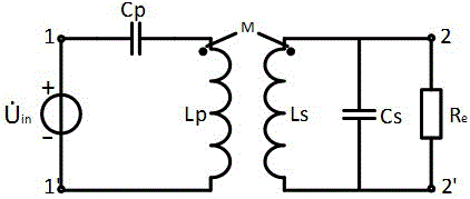
[0137] Embodiment 1: For a wireless power transmission system operating at a frequency of 100kHz, the self-inductance of the primary side of the magnetic coupling structure is 150uH, the self-inductance of the secondary side is 130uH, and the mutual inductance between the primary side and the secondary side is 30uH. It is 100V, and the method of optimization using the new SP compensation method is as follows:

[0138] When the output requires 1A, by Get n to be 0.687267, use the parameters of the above formula (1) to design C p 23.82nF, C s is 23.16nF, at this time the output side can achieve the effect of constant current output 1A, the simulation results are as follows Figure 25 shown;

[0139] When the output needs 2A, the calculated n is 1.186375, and the parameters of formula (1) are used to design C p 20.31nF, C s is 26.83nF, at this time the output side can achieve the effect of constant current output 2A, the simulation results are as follows Figure 26 shown; ...


PUM


Abstract

The invention relates to a resonance compensation method for a wireless power transmission system with a random constant-current output. According to the method, all-range accurate regulation on an output current is achieved through a controllable leakage inductance compensation method under the condition of not changing existing SP and PP compensation network structures, and the method has the characteristics of being wide in output current range, high in practicability, simple, easy to use and the like.

Description

technical field [0001] The invention relates to a new compensation network parameter determination method, in particular to a resonance compensation method for a wireless power transmission system with arbitrary constant current output. Background technique [0002] The wireless power transmission technology is to rectify the alternating current of the power grid, correct the power factor and invert it into high-frequency alternating current. Through the compensation network and magnetic coupling system, the energy is transmitted from the transmitting side to the receiving side, and then through the rectification link and power voltage regulation. After the link, the output supplies power to the load. The basic structure block diagram of the wireless power transmission system is as follows: figure 1 shown. As an important part of the system, the compensation network has an important impact on improving the system power factor, improving input and output characteristics and...

Claims


Application Information

Patent Timeline
IPC IPC(8): H02J50/12
Inventor 陈庆彬叶逢春陈为
Owner FUZHOU UNIV
Why Eureka
Try Eureka