Buck-boost converters and power management integrated circuits including the same

a technology of power management integrated circuits and converters, which is applied in the direction of power conversion systems, dc-dc conversion, instruments, etc., can solve the problems of increasing the capacity of the battery included in the mobile device, increasing the size of the mobile device, and the conversion efficiency of conventional dc-dc converters (e.g., a buck-boost converter, etc., to achieve the effect of efficient management of power supplied, power consumption of internal devices, and power management integrated circui

Active Publication Date: 2017-07-11
SAMSUNG ELECTRONICS CO LTD
View PDF22 Cites 1 Cited by
  • Summary
  • Abstract
  • Description
  • Claims
  • Application Information

AI Technical Summary

Benefits of technology

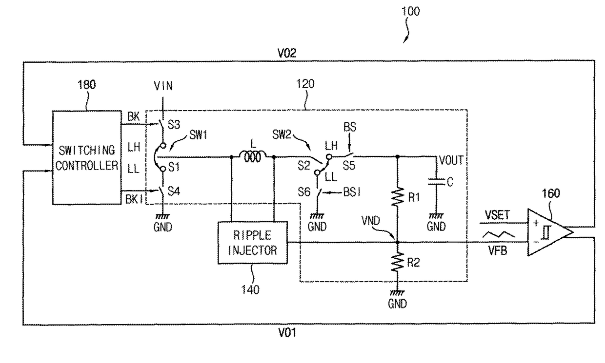
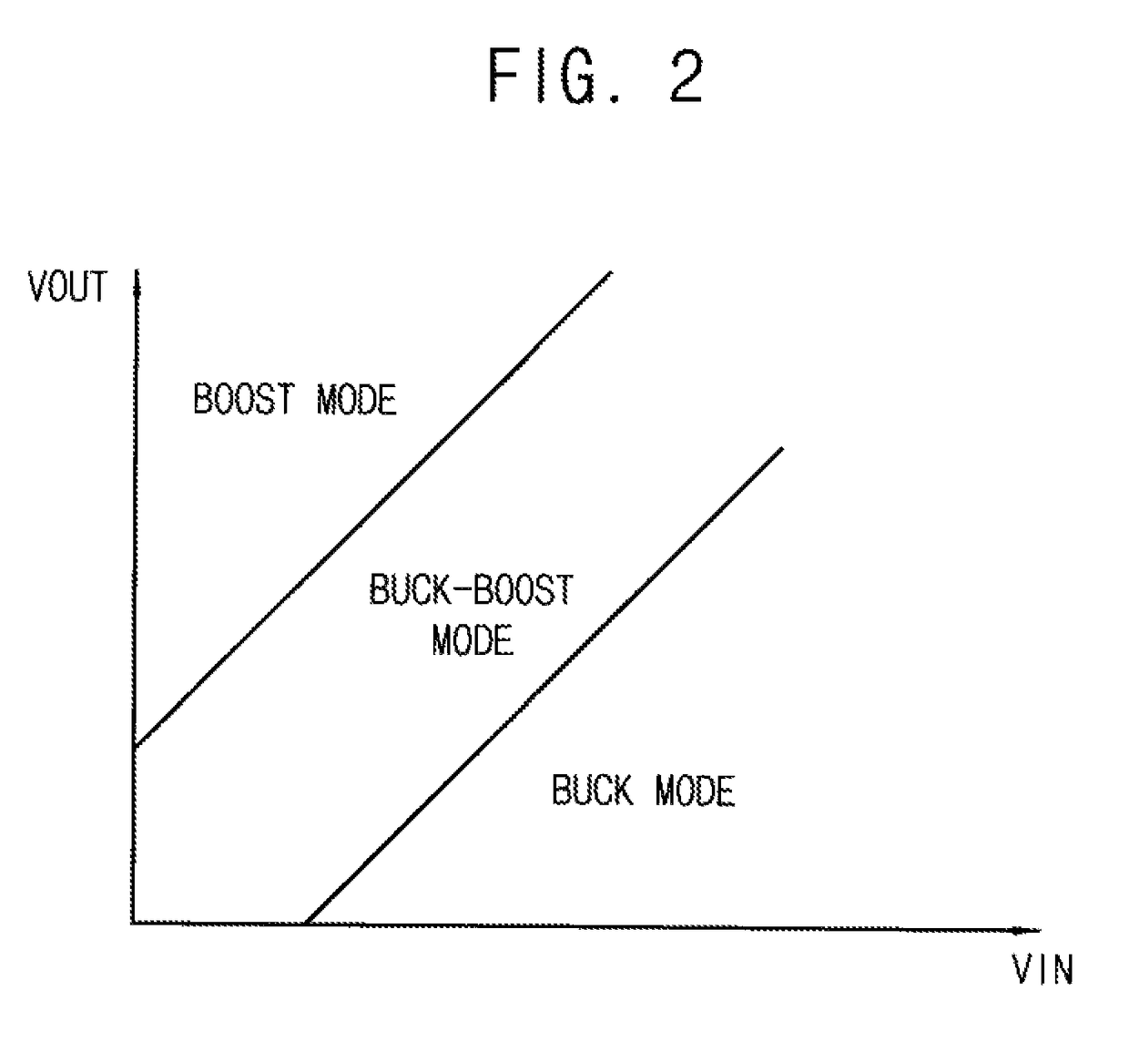
[0038]According to at least some example embodiments, a buck-boost converter may generate a ripple based on switching signals corresponding to switching operations of (or inside) a converting circuit, may output a switching control signal by comparing an output control voltage with a feedback voltage that is generated by adding the ripple to a divided voltage that is generated by performing a voltage division on an output voltage, and may change a current flow path of the converting circuit based on the switching control signal in a buck mode, a buck-boost mode, and a boost mode when the buck-boost converter converts an input voltage (e.g., a direct-current (DC) voltage) into an output voltage (e.g., a DC voltage). Thus, using one input voltage, the buck-boost converter may output an output voltage that is stepped down from the input voltage (e.g., in the buck mode), may output an output voltage having a voltage level that is relatively close to a voltage level of the input voltage (e.g., in the buck-boost mode), and may output an output voltage that is stepped up from the input voltage (e.g., in the boost mode). In other words, according to at least some example embodiments, the buck-boost converter may output the output voltage having a wider output range as compared to conventional buck-boost converters. Here, the buck-boost converter may achieve relatively high (or improved) conversion efficiency because the buck-boost converter operates based on a hysteresis-based control.
[0039]According to at least some example embodiments, a power management integrated circuit may more efficiently manage power supplied by a battery (or other power supply) by including the buck-boost converter. Thus, power consumption of internal devices (e.g., a processor, a memory device, etc.) included in an electronic device (e.g., a mobile device, etc.) having the power management integrated circuit may be reduced.

Problems solved by technology

However, increasing the capacity of the battery included in the mobile device has a limit because increasing battery capacity of mobile devices may result in increased size of the mobile devices.
However, conventional DC-DC converters (e.g., a buck-boost converter, etc.) have relatively low conversion efficiency when a voltage level of an input voltage is relatively close to a voltage level of an output voltage.

Method used


Image

  • Buck-boost converters and power management integrated circuits including the same
  • Buck-boost converters and power management integrated circuits including the same
  • Buck-boost converters and power management integrated circuits including the same

Examples


Embodiment Construction

[0059]Various example embodiments will be described more fully with reference to the accompanying drawings, in which some example embodiments are shown. Inventive concepts may, however, be embodied in many different forms and should not be construed as limited to the embodiments set forth herein. Rather, these embodiments are provided so that this disclosure will be thorough and complete, and will fully convey the scope of inventive concepts to those skilled in the art. Like reference numerals refer to like elements throughout this application.

[0060]It will be understood that, although the terms first, second, etc. may be used herein to describe various elements, these elements should not be limited by these terms. These terms are used to distinguish one element from another. For example, a first element could be termed a second element, and, similarly, a second element could be termed a first element, without departing from the scope of inventive concepts. As used herein, the term ...


PUM


Abstract

A buck-boost converter includes: a converting circuit; a ripple injector; a hysteresis comparator; and a switching controller. The converting circuit is configured to generate an output voltage by adjusting an input voltage in a buck mode, a boost mode, and a buck-boost mode. The ripple injector is configured to generate a ripple based on switching signals corresponding to switching operations of the converting circuit. The hysteresis comparator outputs at least one switching control signal by comparing an output control voltage with a feedback voltage generated by adding the ripple to a divided voltage generated by performing a voltage division on the output voltage. The switching controller is configured to change a current flow path of the converting circuit based on the at least one switching control signal.

Description

CROSS-REFERENCE TO RELATED APPLICATION(S)[0001]This application claims priority under 35 USC §119 to Korean Patent Application No. 10-2014-0134256, filed on Oct. 6, 2014 in the Korean Intellectual Property Office (KIPO), the entire contents of which are incorporated herein by reference.BACKGROUND[0002]Technical Field[0003]Example embodiments relate generally to DC-DC converters. More particularly, example embodiments of inventive concepts relate to buck-boost converters capable of selectively operating in one of a buck mode, a buck-boost mode, and a boost mode, and power management integrated circuits including buck-boost converters.[0004]Description of the Related Art[0005]Recently, as mobile devices (e.g., smart phones, etc.) are more widely used in various fields of application, most mobile device manufacturers are trying to increase battery capacity of mobile devices to increase hours of use of the mobile devices. However, increasing the capacity of the battery included in the m...

Claims


Application Information

Patent Timeline
Patent Type & Authority Patents(United States)
IPC IPC(8): H02M3/158H02M3/156
CPCH02M3/1582H02M3/1563
Inventor CHO, MIN-SOOHAN, JAE-YEOLKEUM, DONG-JINSOHN, IL-YOUNGKUDO, RYOTARO
Owner SAMSUNG ELECTRONICS CO LTD
Why Eureka
Try Eureka