Separation and suction integrated device

An integrated, attracting head technology, applied in the field of medical related technical equipment, can solve problems such as damage to healthy tissues, and achieve the effect of reducing damage

Active Publication Date: 2016-07-13
SHANDONG TUMOR HOSPITAL
View PDF13 Cites 0 Cited by
  • Summary
  • Abstract
  • Description
  • Claims
  • Application Information

AI Technical Summary

Problems solved by technology

In this process, if there is healthy tissue between the upper hollow forceps body and the outer positioning tube, this part of healthy tissue will inevitably be damaged.

Method used


Image

  • Separation and suction integrated device
  • Separation and suction integrated device
  • Separation and suction integrated device

Examples


Embodiment 1

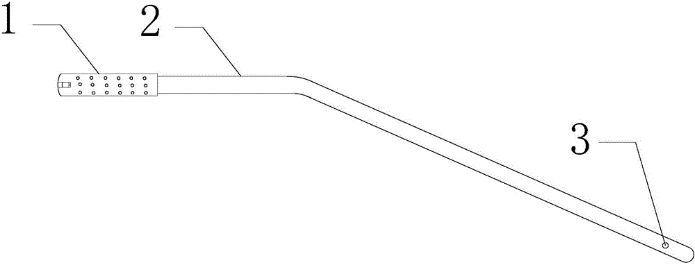
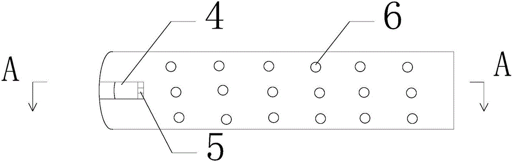
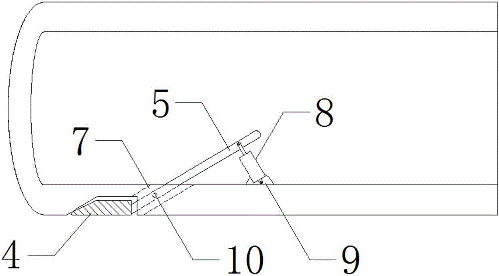
[0089] Embodiment 1: A kind of separation and attraction integrated device, its structure is as follows Figure 1-3 As shown, the suction device body 2 includes a hollow structure, the front end of the suction device body 2 is a suction head 1, and the suction head 1 has a plurality of suction holes 6, and the suction head 1 is an arc-shaped structure. There is a clamping block 4 on the side wall of the suction head 1, and the clamping block 4 is assembled with the suction head 1 through a rotating shaft. The front end of the clamping block 4 is airtightly attached to the suction head 1 , but there is still a certain distance from the end of the suction head 1 . The rear end of the clamping block 4 is fixedly connected with the left end of the rotating rod 5 , and the right end of the rotating rod 5 is driven by the first power mechanism 8 .

[0090] According to different needs, the first power mechanism 8 can be an oil cylinder, the piston rod of the oil cylinder is hinged ...

Embodiment 2

[0098] Embodiment 2: A kind of separation and attraction integrated device, its structure is as follows Figure 5-7 As shown, the suction device body 2 includes a hollow structure, the front end of the suction device body 2 is a suction head 1, and the suction head 1 has a plurality of suction holes 6, and the suction head 1 is an arc-shaped structure. There is a clamping block 4 on the side wall of the suction head 1 , and the clamping block 4 is assembled with the suction head 1 through a rotating shaft 10 . The front end of the clamping block 4 is airtightly attached to the suction head 1 , the rear end of the clamping block 4 is fixedly connected to the left end of the rotating rod 5 , and the right end of the rotating rod 5 is driven by the first power mechanism 8 .

[0099] According to different needs, the first power mechanism 8 is an oil cylinder, the piston rod of the oil cylinder is hinged with the end of the rotating rod 5, the cylinder body of the oil cylinder is ...

Embodiment 3

[0109] Embodiment 3: A kind of separation and attraction integrated device, its structure is as follows Figure 9-11 As shown, the suction device body 2 includes a hollow structure, the front end of the suction device body 2 is a suction head 1, and the suction head 1 has a plurality of suction holes 6, and the suction head 1 is an arc-shaped structure. There is a clamping block 4 on the side wall of the suction head 1, and the bottom surface of the clamping block 4 is airtightly attached to the suction head 1. The left and right ends of the clamping block 4 are hemispherical structures to avoid damage to the tissue .

[0110] On the inner surface of the suction head 1, a first power mechanism 8 is fixedly connected. Preferably, the first power mechanism 8 is a servo motor, and the main shaft of the motor has threads, so that the main shaft of the motor is assembled with the clamping block 4 through a thread pair.

[0111] On both sides of the motor, guide sleeves 13 are res...


PUM


Abstract

The invention relates to a separation and suction integrated device and belongs to the field of medical relevant technical equipment. The separation and suction integrated device mainly comprises an aspirator body of a hollow structure. The front end of the aspirator body is provided with a suction head, multiple suction holes are formed in the suction head, the suction head is of an arc-shaped structure, and a clamping block is arranged on the suction head and closely attached to the suction head; the rear end of the clamping block is fixedly connected with one end of a rotary rod, and the other end of the rotary rod is driven by a first power mechanism; the clamping block is driven by an oil cylinder located in the suction head to get close to the suction head so as to clamp a diaphragm and/or tissue. By improving the structure of an existing aspirator, the device has a clamping function without damaging the original suction head structure, so that the work efficiency of doctors is greatly improved, and operation time is shortened.

Description

technical field [0001] The invention relates to the field of medical-related technical equipment, in particular to a separation and suction integrated device. Background technique [0002] The suction device is used to suck the contents of bleeding, exudate, pus, and chest viscera during the operation, so as to make the operation clear and reduce the chance of contamination. [0003] The principle of the suction device is very simple, that is, by connecting the back end of the suction device with a negative pressure source, using the external atmospheric pressure, the material outside the suction head is squeezed into the suction head, and after the material enters the inside of the suction device through the suction hole, the suction is completed. The "attract" effect. [0004] Structurally, most existing suction devices include a curved or straight suction body. The suction body is hollow. The front of the suction body is a suction head with a plurality of suction holes. ...

Claims


Application Information

Patent Timeline
Patent Type & Authority Applications(China)
IPC IPC(8): A61M1/00A61B17/28
CPCA61B2017/2808A61M1/84
Inventor 李辉张永明李兆敏张爱新李子海张百江
Owner SHANDONG TUMOR HOSPITAL
Why Eureka
Try Eureka