Automatic oven lamp holder assembling system

An automatic assembly and lamp holder technology, applied in assembly machines, metal processing equipment, manufacturing tools, etc., can solve problems such as affecting product quality, wasting manpower, and low work efficiency, reducing labor costs and manufacturing costs, and improving assembly and productivity. The effect of manufacturing efficiency and reducing the number of defective products

Inactive Publication Date: 2016-07-13
XIAMEN WALKLONG ELECTRICAL CO LTD
View PDF6 Cites 7 Cited by
  • Summary
  • Abstract
  • Description
  • Claims
  • Application Information

AI Technical Summary

Problems solved by technology

The oven lamp holder in the prior art usually includes a lamp holder main body, a collar, two conductive sheets, two terminals and two rivets. In order to facilitate the assembly device to automatically grab the parts of the oven lamp holder, the conveying device needs to be able to Arranging and outputting the parts of the oven lamp holder, when the existing technology automatically conveys the parts in the oven lamp holder, especially when conveying conductive sheets, terminal blocks and rivets, the parts in the oven lamp holder usually cannot be effectively Sequential arrangement and output, resulting in messy and irregular parts in the output oven lamp holder, it is not convenient for the assembly mechanism to automatically grab and assemble the parts in the messy oven lamp holder, so it is usually necessary to manually adjust the oven lamp holder The placement direction of the parts in the center can meet the requirements of automatic assembly, which not only wastes manpower, but also has low work efficiency and waste of time, which will also affect product quality and cannot realize automation and standardized operations.

Method used


Image

  • Automatic oven lamp holder assembling system
  • Automatic oven lamp holder assembling system
  • Automatic oven lamp holder assembling system

Examples


Embodiment

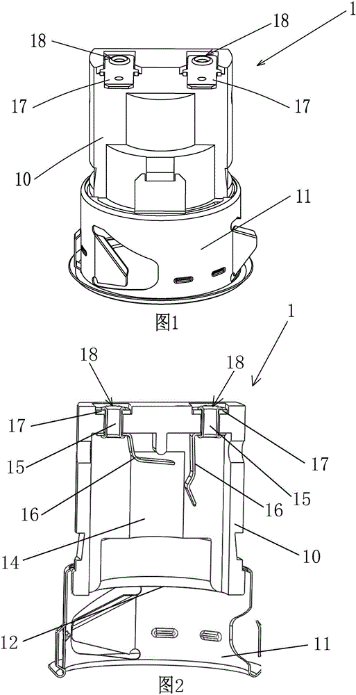
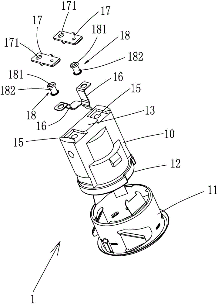
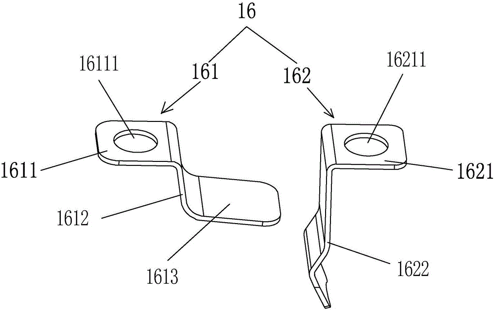
[0065] figure 1 It is the overall structure diagram of the oven lamp holder in the prior art, figure 2 yes figure 1 sectional view of image 3 yes figure 1 For an exploded view, see Figure 1~3 As shown, the lamp holder 1 in the oven includes a lamp holder main body 10, a collar 11, two conductive sheets 16, two connection terminals 17 and two rivets 18, one end of the lamp holder main body 10 is an open end 12, The other end of the lamp holder body 10 is a closed end 13, the collar 11 is sleeved and engaged on the lamp holder body 10 near the opening end 12, and the opening end 12 of the lamp holder body 10 faces the lamp holder body A bulb installation hole 14 is formed extending inside the lamp holder 10, and the bulb installation hole 14 is used for installing and fixing a bulb. One end communicates with the bulb mounting holes 14 respectively, that is, the first ends of the two first through holes 15 all lead to the inner side of the closed end 13 of the lamp holder...


PUM


Abstract

The invention discloses an automatic oven lamp holder assembling system. The system comprises a conveying device and a carrier, the carrier is used for assembly of parts in oven lamp holders, the conveying device is controlled by a central control system, and the carrier is placed on the conveying device and capable of moving along a transmission direction of the conveying device. Two rivet assembling devices, a first conducting strip assembling device, a second conducting strip assembling device, a lamp holder body assembling device, a hoop clamping device and two terminal block assembling devices are sequentially arranged along the transmission direction of the conveying device. The two rivet assembling devices are used for assembling rivets on the carrier; the first conducting strip assembling device is used for assembling first conducting strips on the carrier; the second conducting strip assembling device is used for assembling second conducting strips on the carrier; the lamp holder body assembling device is used for assembling lamp holder bodies on the carrier; the hoop clamping device is used for assembling hoops on the carrier; the two terminal block assembling devices are used for assembling terminal blocks on the carrier. The automatic oven lamp holder assembling system has the advantages that automatic production and assembly of the oven lamp holders can be realized, and assembling and manufacturing efficiency is improved.

Description

technical field [0001] The invention relates to the technical field of automatic production of oven lamp holders, in particular to an automatic assembly system for oven lamp holders. Background technique [0002] An oven lamp is usually provided in the oven, which can play the role of illumination. In order to fix and install the oven light, a lamp holder needs to be installed in the oven. At present, oven lamp holders used for oven lamps are basically assembled manually. Due to the increase in labor costs, the overall production cost increases, and the quality of manually produced lamp holders often cannot meet the standardization requirements. The quality of the lamp holders is uneven. The lamp holders are produced manually, the production efficiency is low, and there are often defective products, resulting in a waste of resources and affecting product sales. Therefore, in order to solve these problems, it is necessary to automate the production of oven lamp holders. ...

Claims


Application Information

Patent Timeline
Patent Type & Authority Applications(China)
IPC IPC(8): B23P21/00
CPCB23P21/00
Inventor 吴立煌
Owner XIAMEN WALKLONG ELECTRICAL CO LTD
Why Eureka
Try Eureka