Multifunctional water mixing valve with electricity isolating wall
A multi-functional, water-mixing valve technology, applied in multi-way valves, valve details, valve devices, etc., can solve the problems of low utilization rate of waterway box structure space, high cost of metal materials, and easy water pollution, etc. Easy to get dirt, high space utilization, uniform force effect
- Summary
- Abstract
- Description
- Claims
- Application Information
AI Technical Summary
Problems solved by technology
Method used
Image
Examples
Embodiment 1
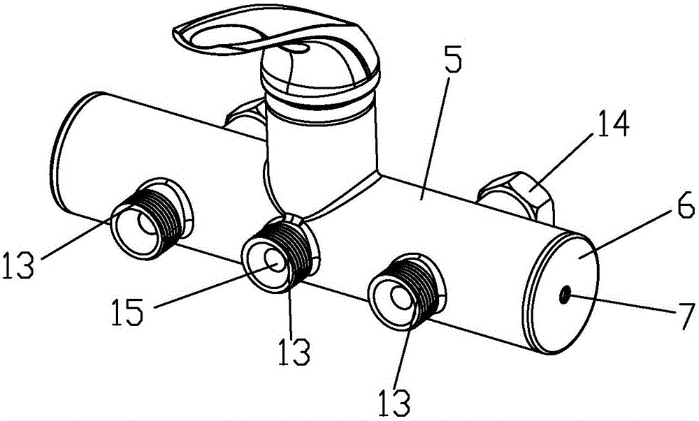
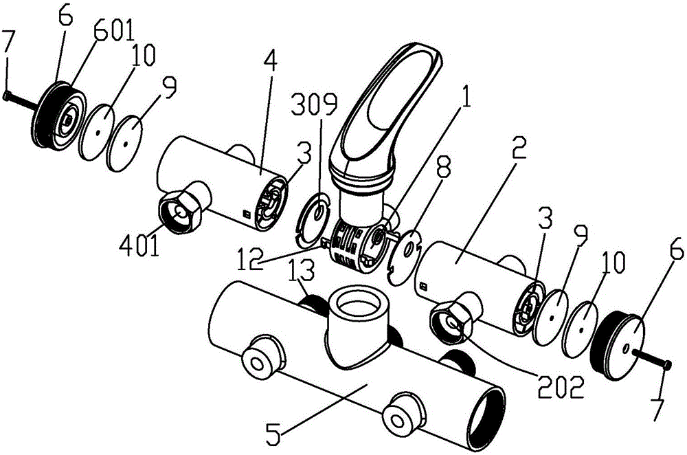
[0044] The working process of embodiment one is: as Figure 5 As shown, the water flow enters the water inlet pipe 2 from the cold water inlet hole 201 and is divided into two branches. One branch walks half a circle in the forward direction to enter the water inlet pipe outlet hole 202 and enters the water heater to be heated. The other branch walks half a circle in the reverse direction from the first A communication hole 309 enters the valve core seat communication body 1; the heated hot water enters the outlet pipe 4 from the outlet pipe inlet hole 401, as Figure 4 As shown, the hot water entering the outlet pipe 4 is divided into two branches after half a circle of the electricity-isolated waterway in the forward direction, one flows out from the hot water outlet hole 402, and the other branch travels through the other half-circle of the electricity-isolated waterway and then from the first communication hole 309 enters the connecting body 1 of the valve core seat and mi...
Embodiment 2
[0045] Embodiment two is a two-layer electricity-isolated waterway: as Figure 7 to Figure 10 As shown, the water inlet pipe 2 and the water outlet pipe 4 are provided with an inner pipe 303 coaxially arranged with the water pipe to separate the water pipe cavity into an outer layer cavity and an inner layer cavity. There are multiple pieces of second partitions 305 that divide the outer cavity into multiple sub-outer cavities in the radial direction, and multiple pieces are radially set inside the inner tube 303 to separate the inner cavity into multiple sub-inner cavities. The third partition 307 of the cavity, the third partition 307 is fixed between the inner wall of the inner tube 303 and the center column 11, the two ends of the inlet pipe 2 and the outlet pipe 4 are sealed and the second partition is further sealed. 305. The two ends of the third partition 307 are sealed, and the ends of the second partition 305 are alternately provided with second gaps 302 that communi...
PUM
 Abstract
Description
Claims
Application Information
 - R&D
- Intellectual Property
- Life Sciences
- Materials
- Tech Scout
- Unparalleled Data Quality
- Higher Quality Content
- 60% Fewer Hallucinations
Browse by: Latest US Patents, China's latest patents, Technical Efficacy Thesaurus, Application Domain, Technology Topic, Popular Technical Reports.
© 2025 PatSnap. All rights reserved.Legal|Privacy policy|Modern Slavery Act Transparency Statement|Sitemap|About US| Contact US: help@patsnap.com


