Thermal ageing testing apparatus and using method thereof

A testing device and thermal aging technology, applied in the direction of measurement device, single semiconductor device testing, measurement of electricity, etc., can solve the problems of inability to achieve real-time monitoring, inability to improve detection efficiency, and a small number of detections, achieving a large number of tests, Fast and time-saving testing process

Active Publication Date: 2016-07-13
杭州华扬电子有限公司
View PDF10 Cites 9 Cited by
  • Summary
  • Abstract
  • Description
  • Claims
  • Application Information

AI Technical Summary

Problems solved by technology

Moreover, these two methods often require a lot of manpower, and the number of simultaneous detections is small, so the efficiency cannot be guaranteed.
[0003] Chinese patent CN103558563A discloses "Aging Vehicle Used for Aging Test of PCB Board Shipment Power Supply", the device used for thermal aging testing of such components is designed as a mobile vehicle, which is heated by fan circulating hot air, and Compared with the existing technology, the mobility of the test device is increased, but the detection efficiency cannot be substantially improved, and a large number of components cannot be heated, and real-time monitoring cannot be achieved.
And compared to the testing process of the PCB board, the process of installing and removing the components of the LED digital tube before and after testing it takes more time

Method used


Image

  • Thermal ageing testing apparatus and using method thereof
  • Thermal ageing testing apparatus and using method thereof
  • Thermal ageing testing apparatus and using method thereof

Examples


Embodiment Construction

[0029] The present invention will be further described below in conjunction with the accompanying drawings and examples.

[0030] Example.

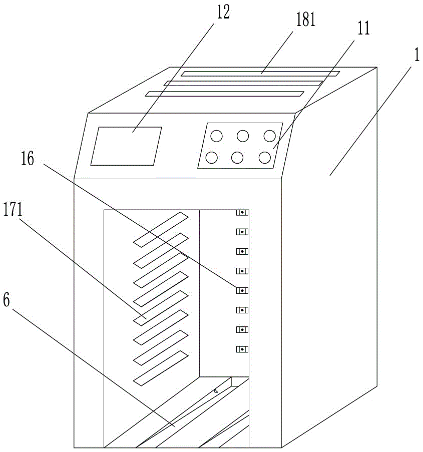
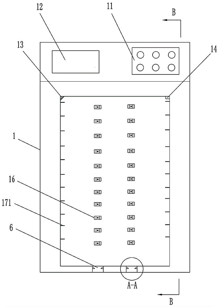
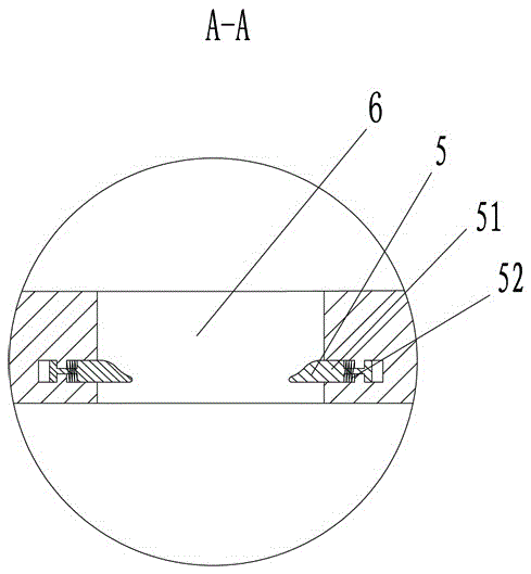
[0031] see Figure 1-Figure 9 , the present invention includes a test box 1 and a feeding device 2, an operation panel 11 is provided outside the test box 1, and a liquid crystal display 12 is provided next to the operation panel 11. A camera 13 and a temperature sensor 14 are arranged in the test box 1 . An air duct 15 is arranged in the two side walls of the test box 1, and a heating device 3 and a fan 4 are arranged at the lower end of the test box 1. The heating device 3 is connected with the air duct 15, and the fan 4 is installed on one side of the heating device 3. The test box 1 is provided with multiple groups of vertically arranged power supply card slots 16, and the test box inner wall on both sides of each group of power supply card slots 16 is provided with an air inlet 17, the test box top is provided with an air outlet 18...


PUM


Abstract

The invention provides a thermal ageing testing apparatus and a using method thereof. The thermal ageing testing apparatus comprises a testing box and a feeding device. A testing box is provided with a liquid crystal display and a camera; a heating device and a fan are arranged at the lower end of the two sides of the testing box; a plurality of groups of power clamp grooves are formed inside the testing box and air inlets are arranged at the inner wall of the testing box at the two sides of multiple groups of power clamp grooves; and an air outlet is formed in the top end of the testing box. The feeding device includes a feeding vehicle and a testing board; a fixed rack is installed on the feeding vehicle and a plurality of fixation positions are arranged on the fixed rack; power connectors are arranged at the rear end of the fixed rack; power ports are arranged at the fixation positions; and the power ports arranged at the rear end of the fixed rack are connected with the power connectors arranged on the fixation positions. The testing board is installed on fixation positions and is connected with the power connectors. A plurality of plugging slots are formed in the testing board. According to the invention, the design is reasonable and the operation is simple; the testing process can be realized rapidly; and the testing number is large and the transport speed is fast. Intelligent heating and cooling are carried out; and the time is saved. Real-time observation is carried out while element testing is carried out.

Description

technical field [0001] The invention is applicable to the field of LED digital tube detection, and in particular relates to a thermal aging test device and a use method thereof. Background technique [0002] During the production process of LED digital tubes, it is necessary to inspect the products and eliminate defective products. Now the main detection method is through manual visual detection. Make the LED digital tubes to be checked display numbers and English letters respectively to judge whether the LED digital tubes can display normally. This method requires a lot of labor and often makes mistakes. After the display test is carried out, it is also necessary to carry out thermal aging test on the LED digital tube. In the prior art, the LED digital tube is directly put into the aging box for thermal aging simulation, and after the thermal aging simulation is completed, it is taken out, and then the LED digital tube is energized for inspection. Moreover, these two met...

Claims


Application Information

Patent Timeline
Patent Type & Authority Applications(China)
IPC IPC(8): G01R31/26
CPCG01R31/2601
Inventor 马怡平
Owner 杭州华扬电子有限公司
Why Eureka
Try Eureka