
Improved double-energy CT imaging method and apparatus

A CT imaging, low-energy technology, applied in the direction of measuring devices, nuclear radiation exploration, material analysis using wave/particle radiation, etc., can solve the problems of high detector cost, high cost, data redundancy, etc.

Inactive Publication Date: 2016-07-13
THE FIRST RES INST OF MIN OF PUBLIC SECURITY +1
View PDF9 Cites 12 Cited by
  • Summary
  • Abstract
  • Description
  • Claims
  • Application Information

AI Technical Summary

Problems solved by technology

The second is to use two ray sources, two detectors, and set different tube voltages for the two ray sources. This kind of equipment costs a lot
The fourth is to use a double-layer detector, that is, pseudo dual-energy imaging, and the cost of the detector is relatively high
The fifth is to use photon counting detectors for energy spectrum imaging. This technology is still in the laboratory research stage, and the cost of the detectors is still very high
[0003] The patent document with the patent application number 201410294426.2 discloses a pseudo-dual-energy X-ray linear array imaging system, which adds aluminum foil and copper sheets between the low-energy detection chip and the high-energy detection chip to form a pseudo-dual-energy detection module. There are many detectors, the equipment cost is high, and there is a large amount of data redundancy in image reconstruction

Method used


Image

  • Improved double-energy CT imaging method and apparatus
  • Improved double-energy CT imaging method and apparatus
  • Improved double-energy CT imaging method and apparatus

Examples


Embodiment 1

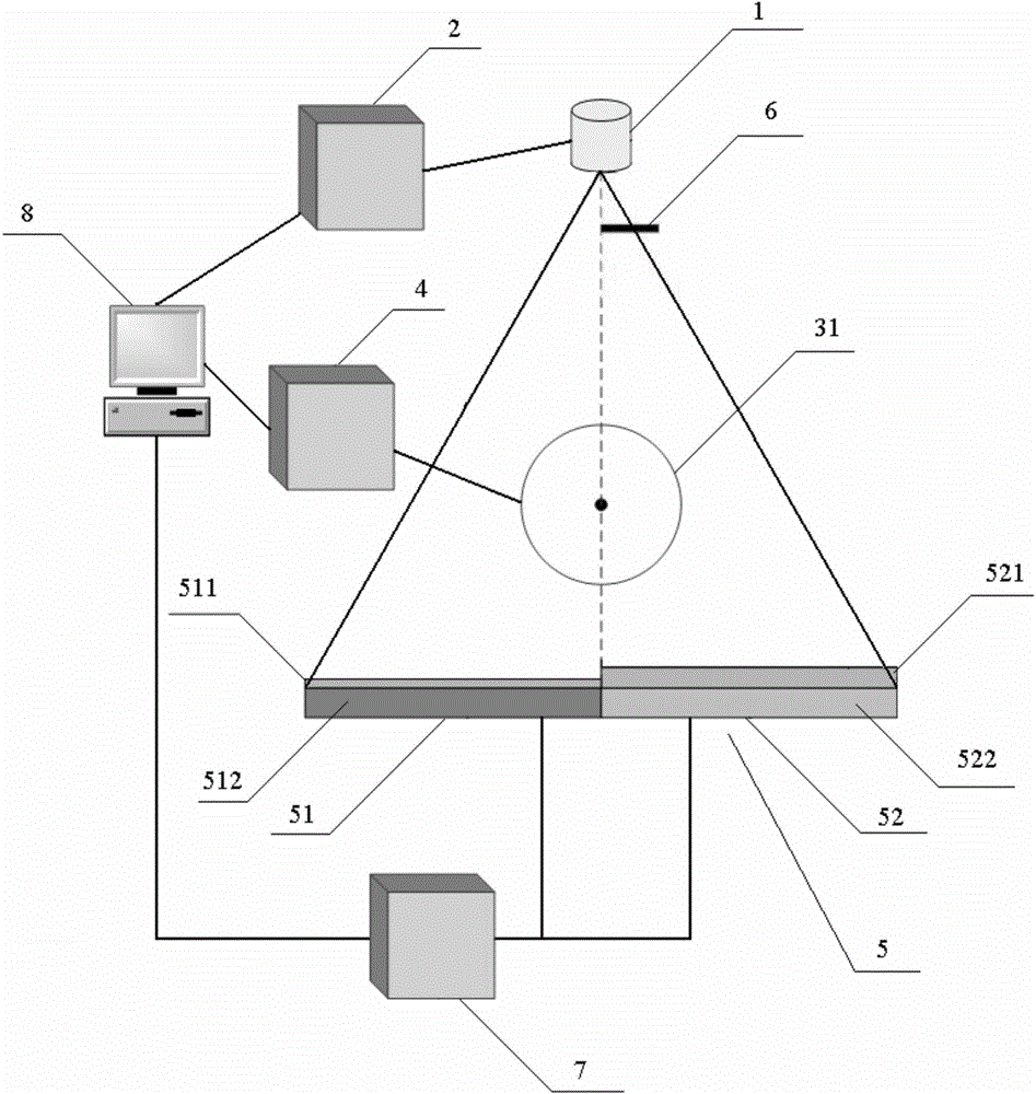
[0056] figure 1 It shows a connection diagram of the improved dual-energy CT imaging device of the present invention, and the rotating mechanism in the figure is a turntable. In this embodiment, the device of the present invention is an imaging mode based on the rotation of the turntable, that is, the scanning object rotates, and neither the ray source nor the single-layer detector rotates.

[0057] Such as figure 1 Shown, the improved dual-energy CT imaging method of the present invention, comprises the steps:

[0058] (1) scan the scanning object with an improved dual-energy CT imaging device, the left half 51 of the single-layer detector 5 collects low-energy projection data, and the right half 52 of the single-layer detector 5 collects high-energy projection data;

[0059] (2) According to the conjugate projection principle of CT scanning projection data, the low-energy projection data collected by the left half 51 of the single-layer detector 5 obtains the low-energy pr...

Embodiment 2

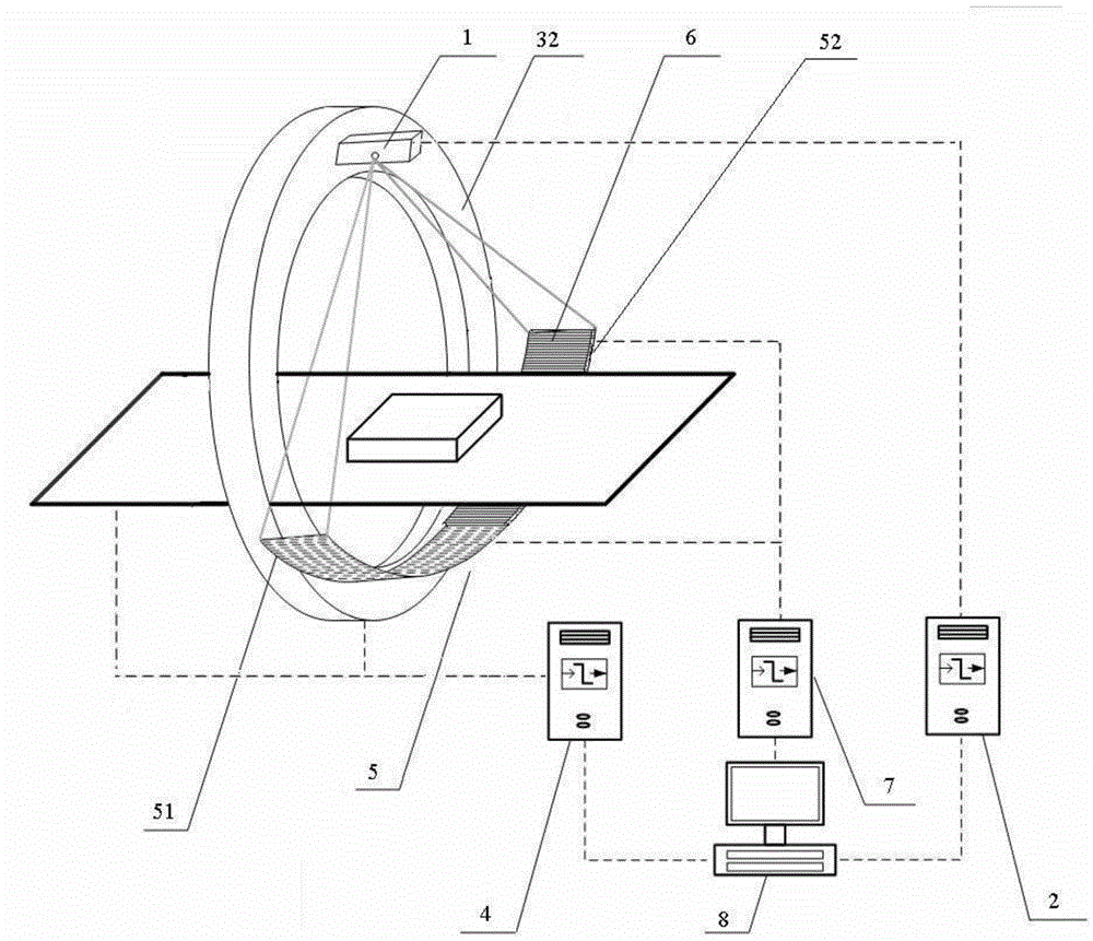
[0073] figure 2 A schematic structural view of the improved dual-energy CT imaging device according to the present invention is shown. In the figure, the rotating mechanism is a frame with a slip ring. In this embodiment, the device of the present invention is an imaging mode based on slip ring rotation, that is, the ray source and the single-layer detector rotate with the rack with the slip ring, and the scanning object then moves in parallel, such as figure 2 shown.


PUM


Abstract

The invention relates to an improved double-energy CT imaging method and apparatus, and belongs to the field of CT imaging. The apparatus scans a scanning object, the left half portion of a single-layer detector acquires low-energy projection data, the right half portion of the single-layer detector acquires high-energy projection data, according to a conjugation projection principle, equivalent low-energy projection data of the right half portion is obtained through the low-energy projection data of the left half portion of the single-layer detector, the equivalent high-energy projection data of the left half portion is obtained through the high-energy projection data of the right half portion of the single-layer detector, and then data processing and image reconstruction are carried out. The apparatus comprises a radiation source, a radiation source controller, a rotation mechanism, a motion controller, the single-layer detector, a metal filter, a data acquisition controller and a maser control computer. The left half portion of the single-layer detector comprises a low-energy detection element, and the right half portion comprises a high-energy detection element. The method and apparatus provided by the invention decrease the detector cost by nearly 50%.

Description

technical field [0001] The invention relates to an improved dual-energy CT imaging method and device, belonging to the field of CT (Computed Tomography, ie computerized tomography) imaging, in particular to the field of security inspection CT imaging. Background technique [0002] At present, dual-energy CT imaging modes usually have the following types: one is to obtain projection data under two high voltages by switching the high voltage of the ray source, and this method usually scans the object twice. The second is to use two ray sources, two detectors, and set different tube voltages for the two ray sources. The cost of such equipment is very high. The third is through the rapid switching of the radiation source. This method has relatively high requirements on the radiation source. The above three cases are true dual-energy imaging. The fourth is to adopt double-layer detectors, that is, pseudo dual-energy imaging, and the cost of the detectors is relatively high. Th...

Claims


Application Information

Patent Timeline
IPC IPC(8): G01V5/00G01N23/087
Inventor 李保磊张耀军张萍宇莫阳李斌
Owner THE FIRST RES INST OF MIN OF PUBLIC SECURITY
Learn More