
Transformer high-voltage outgoing line integration system

A high-voltage outlet, transformer technology, applied in the direction of transformer/inductor coil/winding/connection, transformer/inductor parts, electrical components, etc., can solve the problem that the spacing does not meet the minimum spacing requirements, the power plant layout occupies a large area, etc. problems, to achieve the effect of reducing the space occupied by the layout, reducing the space occupied, and ensuring the safety of operation

Active Publication Date: 2018-05-25
CHINA ENERGY ENG GRP GUANGDONG ELECTRIC POWER DESIGN INST CO LTD
View PDF5 Cites 0 Cited by
  • Summary
  • Abstract
  • Description
  • Claims
  • Application Information

AI Technical Summary

Problems solved by technology

Since the overhead terminals of the transformer are exposed to the air, in order to prevent the pollution and flashover of the overhead terminals of the transformer during the layout design of the power plant, the distance between other equipment such as natural ventilation cooling towers, mechanical ventilation cooling towers and outdoor high-voltage power distribution devices There are requirements, generally the minimum spacing is required to be 40m, so that the area occupied by the layout of the power plant is large
And in some projects, due to the limited layout space, the distance between other equipment such as natural ventilation cooling towers, mechanical ventilation cooling towers and outdoor high-voltage power distribution devices cannot meet the minimum distance requirements, so it is impossible to prevent the overhead terminals of transformers from collapsing. Outlet pollution flashover problem affects the operation safety of the power plant

Method used


Image

  • Transformer high-voltage outgoing line integration system
  • Transformer high-voltage outgoing line integration system

Examples


Embodiment Construction

[0021] Embodiments of the present invention are described in detail below in conjunction with accompanying drawings:

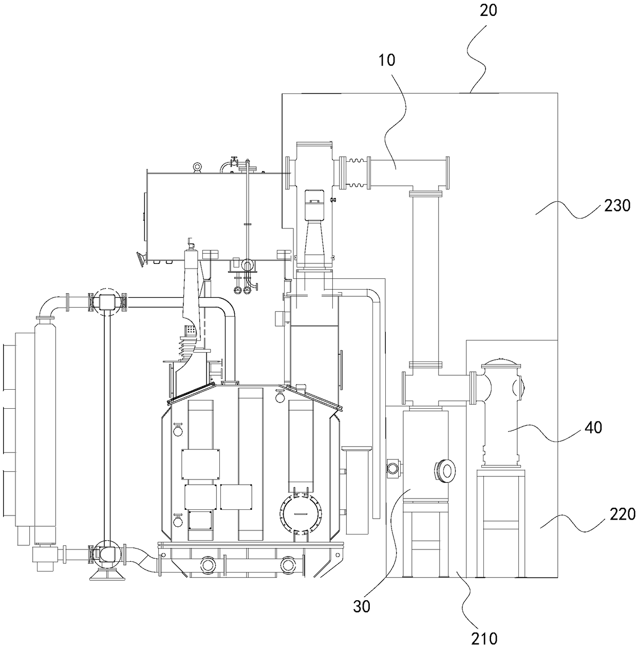
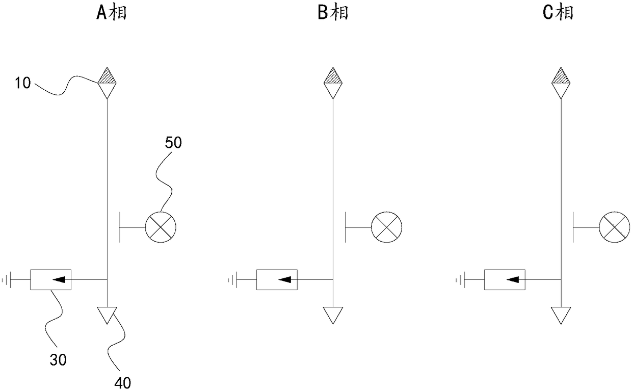
[0022] Such as figure 1 and figure 2 As shown, a transformer high-voltage outgoing line integration system, the transformer is provided with a high-voltage outgoing line terminal 10, the transformer high-voltage outgoing line integration system includes an airtight sleeve 20, a lightning arrester 30, and a high-voltage bushing 40, and the lightning arrester 30, high-voltage bushing 40 and high-voltage outgoing line terminals Both are located in the airtight sleeve 20 , the arrester 30 and the high voltage bushing 40 are respectively electrically connected to the high voltage outlet terminal 10 , and the airtight sleeve 20 is filled with insulating gas.

[0023] The lightning arrester 30, the high-voltage bushing 40 and the high-voltage outlet terminal are arranged in the airtight sleeve 20, and the connection method of the overhead jumper is no longer used, ...


PUM


Abstract

The invention relates to a transformer high-voltage outlet-wire integration system.A high-voltage outlet-wire terminal is arranged on a transformer.The transformer high-voltage outlet-wire integration system comprises a closed sleeve, an arrester and a high-voltage sleeve pipe.The arrester, the high-voltage sleeve pipe and a high-voltage side outlet-wire terminal are located in the closed sleeve, the arrester and the high-voltage sleeve pipe are electrically connected with the high-voltage outlet-wire terminal respectively, and the closed sleeve is filled with insulating gas.The arrester, the high-voltage sleeve pipe and the high-voltage side outlet-wire terminal are arranged in the closed sleeve, a connecting mode with aerial jumper wires is not adopted, the closed sleeve is filled with the insulating gas, the high-voltage outlet-wire terminal can not be in contact with external media, pollution flashover of the high-voltage outlet-wire terminal is avoided, and the operation safety of a power plant is guaranteed.When the power plant is arranged and designed, intervals between other devices such as a natural ventilation cooling tower and a mechanical draft cooling tower and an outdoor high-voltage distribution device do not need to be considered, and the occupied space of power plant arrangement is reduced.

Description

technical field [0001] The invention relates to the technical field of power plant layout, in particular to a transformer high-voltage outgoing line integration system. Background technique [0002] In the electrical system of the power plant, considering the convenience of transformer maintenance and repair, and without restrictions, the high-voltage outgoing line of the 220kV main transformer mainly adopts the outgoing line connected by overhead line. Since the overhead terminals of the transformer are exposed to the air, in order to prevent the pollution and flashover of the overhead terminals of the transformer during the layout design of the power plant, the distance between other equipment such as natural ventilation cooling towers, mechanical ventilation cooling towers and outdoor high-voltage power distribution devices There are requirements for both, and the minimum spacing is generally required to be 40m, so that the area occupied by the layout of the power plant i...

Claims


Application Information

Patent Timeline
Patent Type & Authority Patents(China)
IPC IPC(8): H01F27/29H01F27/32
CPCH01F27/292H01F27/321H01F27/325
Inventor 王兴华阳熹张振林睿李全皎李奇赵陆尧
Owner CHINA ENERGY ENG GRP GUANGDONG ELECTRIC POWER DESIGN INST CO LTD
Learn More