Clock synchronization method and device for time calibration boards

A time calibration and clock synchronization technology, which is applied in the field of medical imaging, can solve the problems of wrong time conforming to the judgment result and affecting the quality of subsequent image reconstruction, so as to achieve the effect of improving accuracy and accurate photon time

Active Publication Date: 2016-07-13
SHENYANG NEUSOFT MEDICAL SYST CO LTD
View PDF6 Cites 11 Cited by
  • Summary
  • Abstract
  • Description
  • Claims
  • Application Information

AI Technical Summary

Problems solved by technology

[0004] It can be seen that the clock synchronization between the time calibration boards is very important. Only when the clocks between the time calibration boards are synchronized can the receiving time of the photon be accurately measured, making the time coincidence judgment more accurate; otherwise, if the clocks between the boards are not synchronized, then it is possible Wrong time coincidence judgment results will be generated, such as determining a non-conformity event as a coincidence event, and errors in coincidence judgment will affect the quality of subsequent image reconstruction

Method used


Image

  • Clock synchronization method and device for time calibration boards
  • Clock synchronization method and device for time calibration boards
  • Clock synchronization method and device for time calibration boards

Examples


Embodiment Construction

[0026] Exemplary embodiments will be described in detail herein, examples of which are illustrated in the accompanying drawings. Where the following description refers to the drawings, the same numerals in different drawings refer to the same or similar elements unless otherwise indicated. The implementations described in the illustrative examples below are not intended to represent all implementations consistent with this application. Rather, they are merely examples of apparatus and methods consistent with some aspects of the present application as recited in the appended claims.

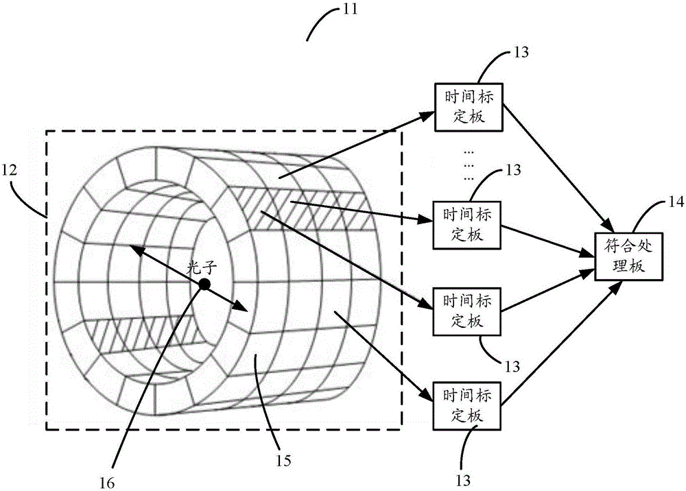
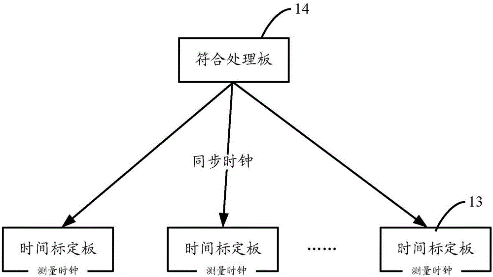
[0027] The embodiment of the present application provides a method for synchronizing the clock of a time calibration board connected to a BLOCK module of a detection device in an imaging technology. For example, the method can be applied to a PET system, so that the time calibration board in the PET system can The calibration of the photon time is more accurate, and the accuracy of the coincidenc...


PUM


Abstract

The invention provides a clock synchronization method and a device for time calibration boards, wherein the method is executed by anyone of to-be-synchronized time calibration boards; the method comprises the steps: a measuring clock for calibrating photon time is generated locally; in the unit clock period of the measuring clock, the clock receives a synchronous clock for performing clock synchronization among the time calibration boards, and position information of a rising edge of the synchronous clock in the unit clock period is calibrated; according to the position information, the phase difference between the measuring clock and the synchronous clock in the unit clock period is determined, and the phase difference is made to serve as a time compensation value; when the measuring clock calibrates the photon time in the unit clock period, the photon time is compensated through the time compensation value. According to the invention, the method and the device improve the accuracy of incident estimation.

Description

technical field [0001] The present application relates to medical imaging technology, and in particular, to a clock synchronization method and device between time calibration boards. Background technique [0002] In the imaging diagnosis technology in the medical field, a certain substance can usually pass through the scanned object, and the detection device receives the substance after passing through the scanned object, and the tissue of the scanned object can be reconstructed according to the received information of the substance. image, and diagnose the lesion of the scanned object according to the image. After the material information is received, the process of reconstructing the image according to the material information affects the efficiency of image reconstruction. For example, Positron Emission Tomograph (PET) system is an advanced molecular imaging diagnostic equipment in today's medical field. When PET is used for diagnosis, a deoxyglucose marker containing a ...

Claims


Application Information

Patent Timeline
IPC IPC(8): H04J3/06A61B6/03
CPCA61B6/037H04J3/0638G01T1/2985G01T7/005H03L7/00
Inventor 宁鹏杨龙梁国栋高鹏贺亮
Owner SHENYANG NEUSOFT MEDICAL SYST CO LTD
Why Eureka
Try Eureka