Welding tool for electric cabinets

A technology for welding tooling and electrical boxes, applied in welding equipment, auxiliary welding equipment, welding/cutting auxiliary equipment, etc., can solve problems such as low failure maintenance rate and failure of electrical boxes to meet requirements, achieve high quality, and ensure welding efficiency. , to ensure the effect of welding quality

Inactive Publication Date: 2016-07-20
YANTAI WALU ROBOT AUTOMATION CO LTD
View PDF7 Cites 15 Cited by
  • Summary
  • Abstract
  • Description
  • Claims
  • Application Information

AI Technical Summary

Problems solved by technology

At the same time, electrical boxes are often used in open-air places, and the electrical boxes produced are also required to be waterproof, explosion-proof, and rust-proof to ensure safe use and low failure maintenance rate
However, the existing artificially welded electrical boxes cannot meet the requirements

Method used


Image

  • Welding tool for electric cabinets
  • Welding tool for electric cabinets
  • Welding tool for electric cabinets

Examples


Embodiment Construction

[0042] Those skilled in the art will be more aware of the above and other objects, advantages and features of the present invention according to the following detailed description of specific embodiments of the present invention in conjunction with the accompanying drawings.

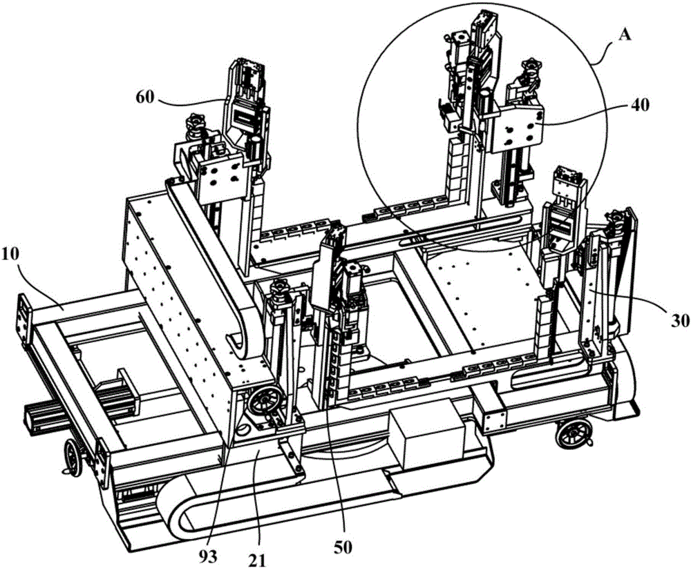
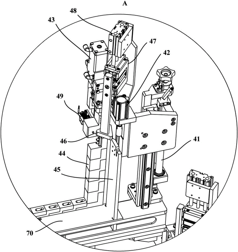
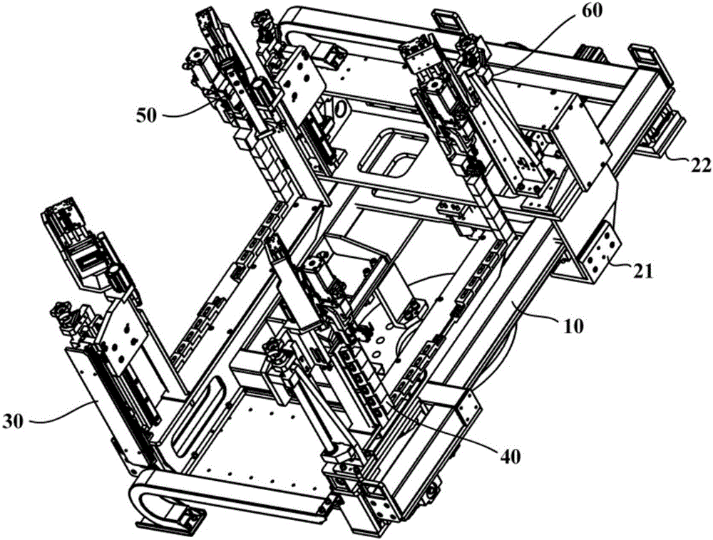
[0043] figure 1 is a schematic structural diagram of a welding tool 200 according to an embodiment of the present invention. Such as figure 1 shown and refer to Figure 2 to Figure 5 , the embodiment of the present invention provides a welding tool 200 for an electrical box 100, which may include a tool bracket 10, a first slide assembly 21, a first clamping device 30, a second clamping device 40, a third clamping device 50 and a fourth clamping device 60 .

[0044] In this embodiment, the tool bracket 10 is used to form the basis of the welding tool 200 and is used to be installed on a positioner so that the robot can weld the electrical box 100 clamped by the welding tool 200 . The tooling bracket ...


PUM


Abstract

The invention provides a welding tool for electric cabinets. The welding tool comprises a tool support, a first sliding plate assembly, a first clamping device, a second clamping device, a third clamping device and a fourth clamping device; the first sliding plate assembly is installed on the tool support in a sliding manner in the transverse direction; the first clamping device is fixed to the tool support and located on one side of the tool support; the second clamping device faces or deviates from the first clamping device and is installed on the tool support in a sliding manner in the longitudinal direction; the third clamping device is fixed to the first sliding plate assembly, and the third clamping device and the first clamping device are located on the same side of the tool support; and the fourth clamping device faces or deviates from the second clamping device and is installed on the first sliding plate assembly in a sliding manner in the longitudinal direction. The first clamping device, the second clamping device, the third clamping device and the fourth clamping device each comprise a compression device and a lifting device, and each lifting device is arranged to driving the corresponding compression device to move in the height direction. The welding tool can be suitable for the electric cabinets in different specifications, the welding efficiency can be guaranteed, and the welding quality can be guaranteed.

Description

technical field [0001] The invention relates to the technical field of electric box welding, in particular to a welding tool for an electric box. Background technique [0002] The electrical box is generally made of U-shaped bending plate (quantity 1 piece), front bending plate (quantity 1 piece), rear bending plate (quantity 1 piece), after assembling spot welding and fixing, and then welding. Q235A or stainless steel with a thickness of 1.5 or 2mm. In existing actual welding, the electrical box after spot welding is directly placed on the workbench, and the manual welding torch is manually held along the welding seam, and the welding posture of the welding torch is swung to complete the welding seam welding work of the entire electrical box . The tempo of on-site manual welding is 10 minutes per piece, and after the welding is completed, experienced manual correction is required, which is very inefficient. In this direct welding method, the electrical box is affected by...

Claims


Application Information

Patent Timeline
Patent Type & Authority Applications(China)
IPC IPC(8): B23K37/04
CPCB23K37/0435
Inventor 张新主计然胡振海陈显东刘华峰
Owner YANTAI WALU ROBOT AUTOMATION CO LTD
Why Eureka
Try Eureka