

High-frequency vibration device for forming holes on sponge by gang drill
A hole-making device and high-frequency vibration technology, which is applied in metal processing and other directions, can solve the problems of simultaneous hole processing, difficulty in hole control, and low efficiency, and achieve stable hole punching process, expanded use range, and simple device structure Effect
- Summary
- Abstract
- Description
- Claims
- Application Information
AI Technical Summary
Problems solved by technology
Method used
Image

Examples
Embodiment 1
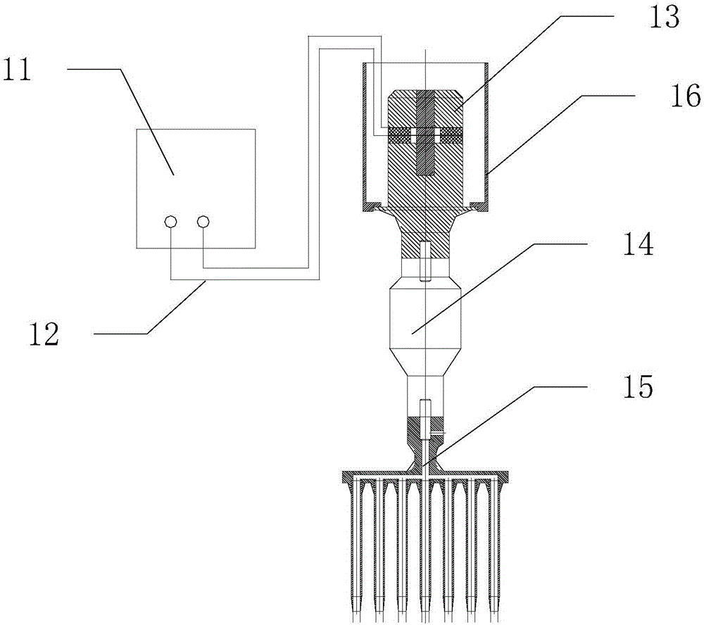
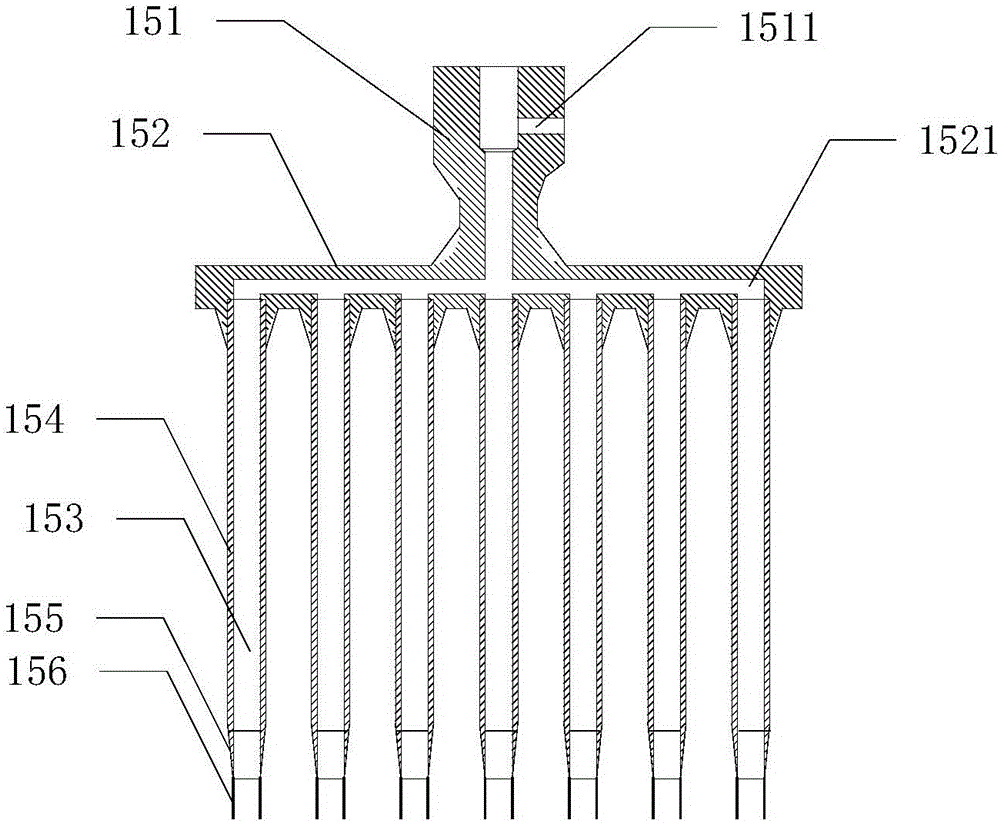
[0031] Such as figure 2 As shown, the multi-tube cutter 15 includes a connecting head 151 connected to the horn 14, a pipe body mounting plate 152 connected to the connecting head 151, and an internal cavity 153 is set on the pipe body mounting plate 152. A plurality of tube bodies 154 , a cutting edge 155 extending from one end of the tube body 154 and a pair of positioning pins 156 on the edge of the cutting edge 155 .
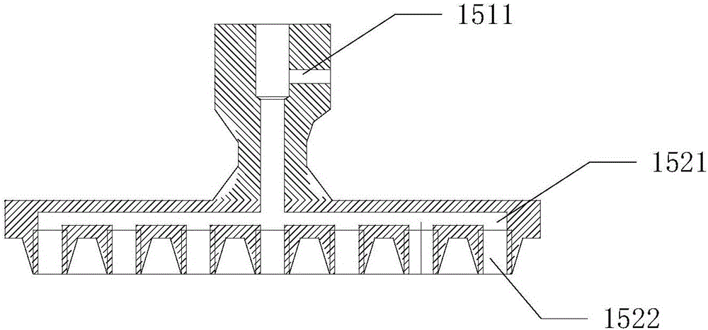
[0032] Such as image 3 As shown, the tube body mounting plate 152 is integrally formed with the connector 151, the connector 151 is provided with a channel 1511, the tube body mounting plate 152 is provided with an air distribution channel 1521, and one end of the channel 1511 is connected to the external The air compressor (not shown in the figure) communicates, and the other end links to each other with the general head of described air distribution channel 1521, as figure 2 As shown, each branch of the branch air channel 1521 communicates with the in...
Embodiment 2
[0036] The difference from Embodiment 1 is that the tube body mounting plate 152 also includes a cover 1523 for the internally threaded hole 1522 . It is used to close the internally threaded hole 1522 that is not connected to the pipe body 154 .
[0037] For example, when the pre-machined hole is large, such as Figure 5 As shown, the external thread head 1541 of the pipe body 154 matches the internal thread hole 1522, the cavity 153 matches the size of the pre-processed hole, and the upper and lower diameters of the pipe body 154 are not uniform.
[0038] Such as Figure 6 As shown, since the cavity 153 becomes larger, the tube bodies 154 cannot be sequentially arranged on the tube body mounting plate 152 , and the unused internal threaded holes 1522 are closed by the cover 1523 .
[0039] Briefly describe the processing process, put the sponge to be processed under the multi-tube cutter 15, after alignment, start the device, the multi-tube cutter 15 passes through the spo...
PUM
| Property | Measurement | Unit |
|---|---|---|
| Arc radius | aaaaa | aaaaa |
Abstract
Description
Claims
Application Information