Rail vehicle traction inverter system and method for integrated energy storage device charging and discharging control

A traction inverter system, charge and discharge control technology, applied in the field of rail vehicle traction inverter system, can solve the problems of high comprehensive cost of equipment, low real-time performance and reliability, complex system, etc., to improve energy utilization rate, improve Effect of controlling real-time performance and reliability, simplifying hardware circuit

Active Publication Date: 2016-07-20
CRRC QINGDAO SIFANG ROLLING STOCK RES INST
View PDF6 Cites 19 Cited by
  • Summary
  • Abstract
  • Description
  • Claims
  • Application Information

AI Technical Summary

Problems solved by technology

The system is relatively complex, and the overall cost of the equipment is relatively high
[0004] On the other hand, the DCDC controller of the on-board energy storage device needs a separate controller for charge and discharge control. To optimize the energy management of the traction inverter under traction and braking conditions, a large number of interactions with the traction inverter are required. Real-time data interaction requires an additional communication cable between the DCDC controller and the traction controller, and the real-time and reliability of the control are relatively low

Method used


Image

  • Rail vehicle traction inverter system and method for integrated energy storage device charging and discharging control
  • Rail vehicle traction inverter system and method for integrated energy storage device charging and discharging control
  • Rail vehicle traction inverter system and method for integrated energy storage device charging and discharging control

Examples


Embodiment Construction

[0033] Specific embodiments of the present invention will be further described below in conjunction with the accompanying drawings.

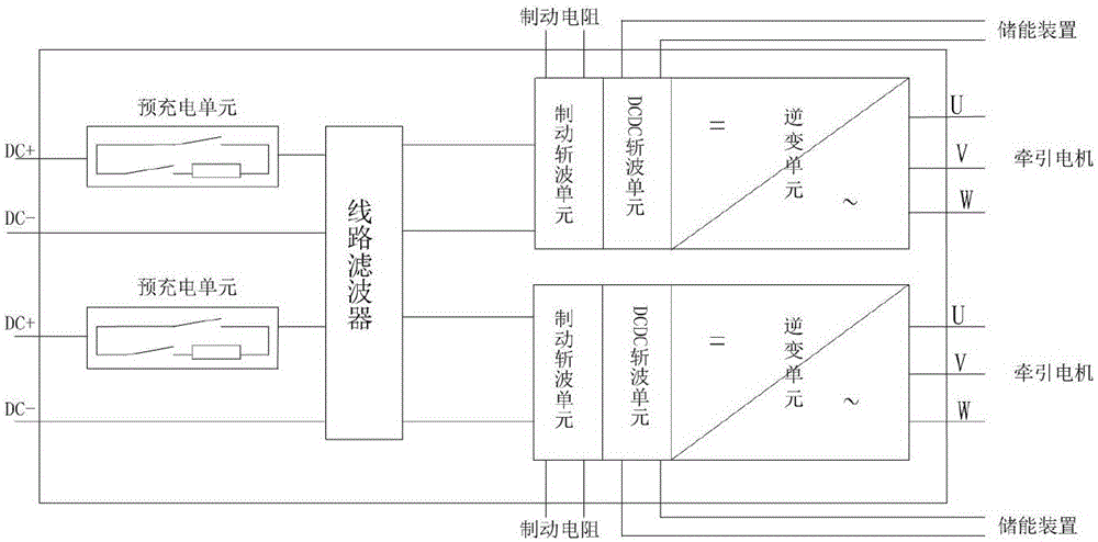
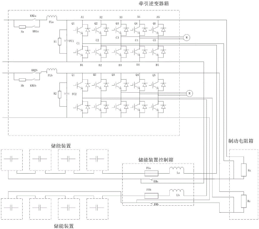
[0034] Such as figure 1 As shown, the rail vehicle traction inverter system integrated with the charge and discharge control of the energy storage device includes a pre-charging unit, a line filter unit, a current and voltage detection unit, two sets of traction inverter units and a control unit.

[0035] There are two groups of pre-charging units and one group of line filtering units; the DC line network side is connected to the input end of a group of line filtering units through two groups of pre-charging units respectively; each group of traction inverter units includes an integrated chopper module and an inverter module, the chopper module includes a brake chopper unit and a DCDC chopper unit, the brake chopper unit is connected to the output end of the line filter unit, the brake resistor and the DCDC chopper unit respectively; the DCDC ch...


PUM


Abstract

Disclosed is a rail vehicle traction inverter system for integrated energy storage device charging and discharging control. The rail vehicle traction inverter system comprises precharging units, a circuit filter unit, a current and voltage detection unit, two sets of traction inverter units and a traction control unit. Current and voltage signals are collected by the current and voltage detection unit, signal conversion is conducted, and the current and voltage signals are sent to the traction control unit. Direct current wire sides are connected to the input end of the set of circuit filter unit through the two sets of precharging units. Each set of traction inverter unit comprises a wave chopping module and an inverter module which are integrated, wherein the wave chopping module comprises a braking wave chopping unit and a DCDC wave chopping unit. The braking wave chopping units are connected with the output end of the circuit filter unit, a braking resistor and the DCDC wave chopping units correspondingly. The DCDC wave chopping units are connected with an energy storage device and an inverter unit correspondingly. The traction inverter units of the rail vehicle traction inverter system are of an integrated structure, so that integration of the DCDC wave chopping units is achieved, a hardware circuit is simplified, and the cost is reduced.

Description

technical field [0001] The invention belongs to the electrical technical field of rail vehicles, and relates to a traction inverter for rail vehicles, in particular to a rail vehicle traction inverter system and method for charging and discharging control of an integrated energy storage device. Background technique [0002] At present, the charge and discharge controller of the energy storage device used in the traction drive system of rail transit generally provides energy for two inverter units with one energy storage device. If a single unit fails, the two traction inverter units cannot be powered by the energy storage device. release and absorption, resulting in poor system redundancy. [0003] At present, the DCDC controller and the traction inverter for charging and discharging the on-board energy storage device are two independent devices, so the DCDC controller also needs a separate set of pre-charging unit, line filter and controller. Requires a separate power modu...

Claims


Application Information

Patent Timeline
Patent Type & Authority Applications(China)
IPC IPC(8): B60L9/00B60L7/22B61C9/38
CPCB60L7/22B60L9/00B60L2200/26B60L2210/40B61C9/38Y02T10/72
Inventor 夏猛张德雨郝玉福毕京斌田以涛盖猛朱孟祥
Owner CRRC QINGDAO SIFANG ROLLING STOCK RES INST
Why Eureka
Try Eureka