Antitheft lock device

An anti-theft lock, a pair of technology, applied in the device to prevent theft of bicycles, transportation and packaging, bicycle accessories, etc., can solve the problems of illegal copying of electronic certificates, installation position restrictions, complicated use process, etc., to achieve large deformation and deformation accuracy High, low-cost effect

Inactive Publication Date: 2016-07-20
NANCHANG INST OF TECH
View PDF6 Cites 2 Cited by
  • Summary
  • Abstract
  • Description
  • Claims
  • Application Information

AI Technical Summary

Problems solved by technology

The magnetic drive anti-theft lock valve mentioned in this article adopts a magnetic drive mechanism. The head end of the magnetic drive anti-theft lock valve is replaced by an ordinary mechanical anti-theft lock. The pressure plate of the valve opening can move up and down, so that the valve is in the open or closed state. However, this method makes the use process complicated and expensive. The magnetic lock is limited by the magnetic force, and the magnetic lock can only be opened in one direction. , the installation position is also limited
U.S. Patent US20160048673A1 proposes an electronic security lock. The electronic security lock uses a

Method used


Image

  • Antitheft lock device
  • Antitheft lock device

Examples


Embodiment 1

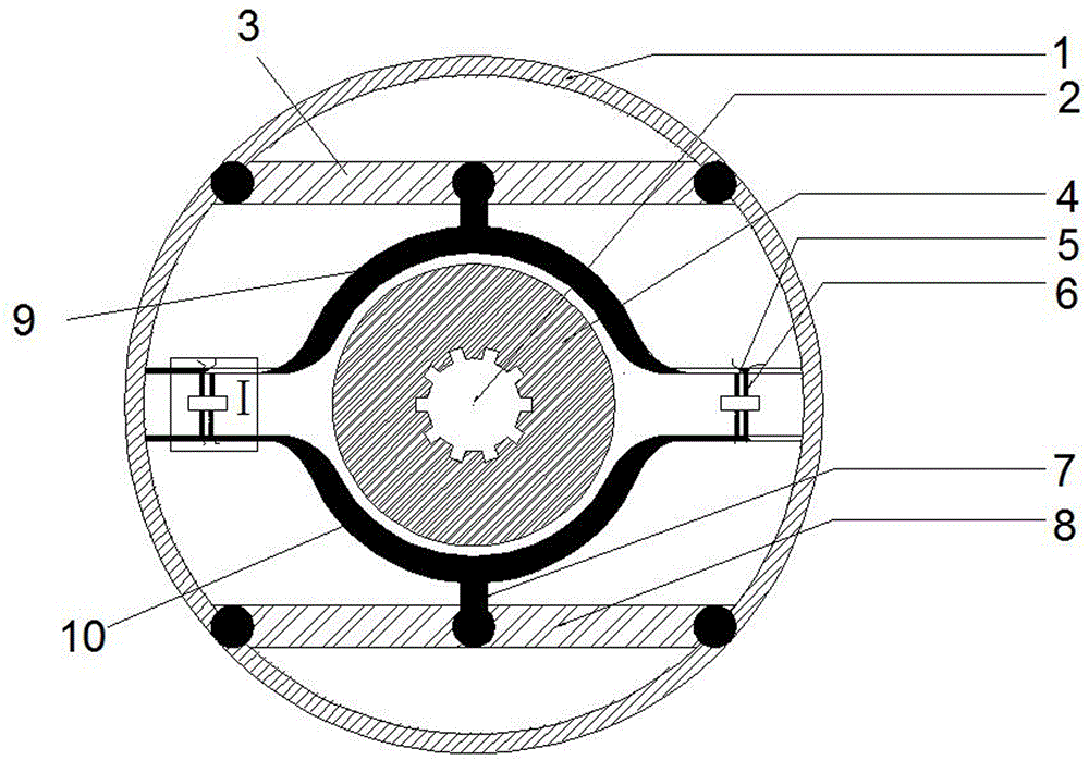
[0019] Example 1, see figure 1 with figure 2 , An anti-theft lock device, which includes a circular support frame 1 and a power supply. A pair of beams are symmetrically provided at the front and rear ends of the circular support frame 1, namely an upper beam 3 and a lower beam 8. The upper beam 3 and the lower beam A pair of brake pads are elastically connected between the beams 8. The brake pads are divided into an upper brake pad 9 and a lower brake pad 10. A set of shape memory alloy springs are respectively arranged between the two corresponding sides of the upper brake pad 9 and the lower brake pad 10 Each group of shape memory alloy springs includes a one-way heat-shrinkable spring 5 and a two-way heat-stretching and cold-shrinking spring 6. In the two groups of shape memory alloy springs, the circuit of the one-way heat-shrinking spring 5 and the two-way heat-stretching The circuits of the cold-shrinkable spring 6 are connected in series with each other through wires, ...

Embodiment 2

[0022] Example 2; see figure 1 with figure 2 , The lower brake pad 10 is fixed on the fixed beam 8 with six fixed springs 7, and both ends of the beam are fixed on the circular support frame 1 by the fixing bolts 3. The circular support frame 1 is screwed and fixed on the wheel hub. Keep a certain gap between the brake pad and the rotating disc 4; the rotating disc 4 and the wheel hub are respectively sleeved on the rotating shaft 2, and the radius of the rotating disc 4 is slightly smaller than the radius of the lower brake pad 10.

[0023] The lower brake pad 10 is semi-elliptical and elastic. Under the deformation of the shape memory alloy spring, the lower brake pad 10 is driven to move, and the rotating disc 4 is slowly held tightly until it locks. The action part of the lower brake pad 10 is mainly half On both sides of the ellipse, the top of the lower brake pad 10 is fixed, so in actual action, a part of the top is an invalid part, which is only used to fix the entire lo...

Embodiment 3

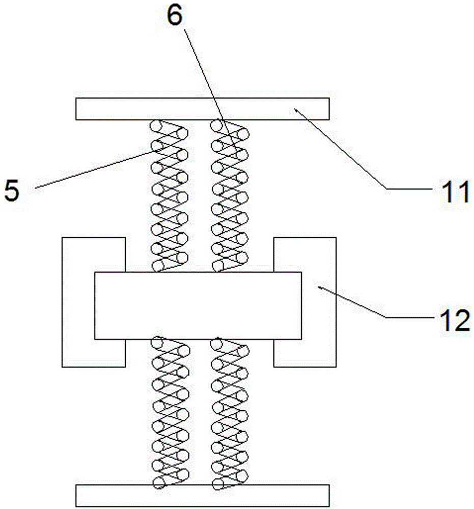
[0024] Example 3; such as figure 2 As shown, the one-way heat-shrinkable spring 5 and the double-way heat-stretching and cold-shrinking spring 6 and the upper and lower brake pads 11, 12 are provided with baffles 11 at the junctions. The baffles 11 are made of insulating materials. The upper brake pad and the lower brake pad are connected as an integral structure; the circuit of the one-way heat-shrinkable spring 5 and the circuit of the two-way heat-stretching and cold-shrinking spring 6 are connected to the power supply through a brake switch and a transformer. The one-way heat-shrinkable spring 5 and the double-way heat-stretching and cold-shrinking spring 6 share a brake switch, and the brake switch has a single-pole double-throw property. The brake switch adopts a double switch, and the circuit of the one-way heat-shrinkable spring 5 and the circuit of the two-way heat-stretching and cold-shrinking spring 6 are respectively connected to both ends of the double switch.

[0...


PUM


Abstract

The invention discloses an antitheft lock device, comprising a circular support frame and a power supply. Cross beams in a pair, upper and lower cross beams, are arranged symmetrically at front and rear ends of the circular support frame, a pair of brake pads are elastically connected between the upper cross beam and the lower cross beam, the brake pads include an upper brake pad and a lower brake pad, a group of shape memory alloy springs are arranged between two corresponding sides of each of the upper brake pad and the lower brake pad, each group of shape memory alloy springs includes a single-travel heat-shrinking spring and a double-travel heat-shrinking cold-contracting spring, and two ends of the single-travel heat-shrinking spring and two ends of the double-travel heat-shrinking cold-contracting spring are connected respectively with the power supply through a brake switch and a transformer. By controlling an input current signal, the shape memory alloy springs are driven so that the brake pads hold a rotary disc, thus locking wheels. The antitheft lock device is simple in structure, easy to mount, low in cost and good for market promotion.

Description

Technical field [0001] The invention relates to an anti-theft lock device. Background technique [0002] At present, two-wheeled and three-wheeled electric vehicles and motorcycles on the market have a low level of anti-theft technology. Most of them can only lock the tires of the car. The anti-theft lock is on the outside of the car body. The lock has a simple structure and single function, which is easy to be picked by thieves. Open question. Today's thieves are pervasive, and unlocking is only a matter of craftsmanship and numbers for them. Most of them are engaged in motor vehicle repair and unlocking technology. They are very familiar with the structure of the vehicle, and are skilled in theft. The main methods are key stabbing and prying. For vehicle locks, disconnection, and connection of vehicle lines, bolt cutters, screwdrivers, cross-breaking tools, multiple types of electric vehicle keys, motorcycle ignition locks and other crime tools are often used, resulting in man...

Claims


Application Information

Patent Timeline
IPC IPC(8): B62L1/02B62H5/18
CPCB62H5/148B62H5/18B62L1/005B62L1/02
Inventor 唐刚徐兵徐斌闫肖肖李志彪邓小珍胡敏候诚邹鹏君杨方毅
Owner NANCHANG INST OF TECH
Why Eureka
Try Eureka