
Indirect energy-efficient emission reduction control method of variable area turbocharged diesel engine

A technology for diesel engines and turbocharging, used in engine control, engine components, combustion engines, etc.

Inactive Publication Date: 2016-07-20
ZHEJIANG UNIV
View PDF5 Cites 8 Cited by
  • Summary
  • Abstract
  • Description
  • Claims
  • Application Information

AI Technical Summary

Problems solved by technology

However, the strong coupling of EGR and AFR actuators makes it difficult to obtain robust results in terms of torque response, output emissions of the engine in steady state and transient state conditions with conventional PI regulators.

Method used


Image

  • Indirect energy-efficient emission reduction control method of variable area turbocharged diesel engine
  • Indirect energy-efficient emission reduction control method of variable area turbocharged diesel engine
  • Indirect energy-efficient emission reduction control method of variable area turbocharged diesel engine

Examples


Embodiment

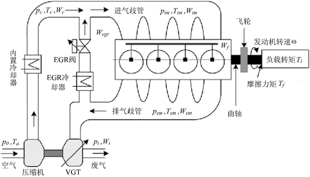
[0122] Taking the common rail direct injection in-line four-cylinder diesel engine produced by a French manufacturer as an example, the speed-gas double-loop control system of the diesel engine is designed.

[0123] 1. Establish a simplified mathematical model. The relevant parameters of the engine are as follows: η m =0.98, T im =313K,V d =0.002m 3 , R=287, μ=0.2829, τ=0.11s, H f =4.601×10 7 J / kg, p 0 =1.01×10 7 Pa, J=0.15kg / m 2 , k im =1.4972×10 7 , k em =1.4608×10 7 , k c =2.0179×10 -6 , k t =3.9241×10 5 .

[0124] Substituting the parameters into the engine control affine model in step c1, the friction and load torque of the speed loop are as follows Figure 4 shown.

[0125] 2. Design the speed loop controller. The parameter K=20 of the design controller.

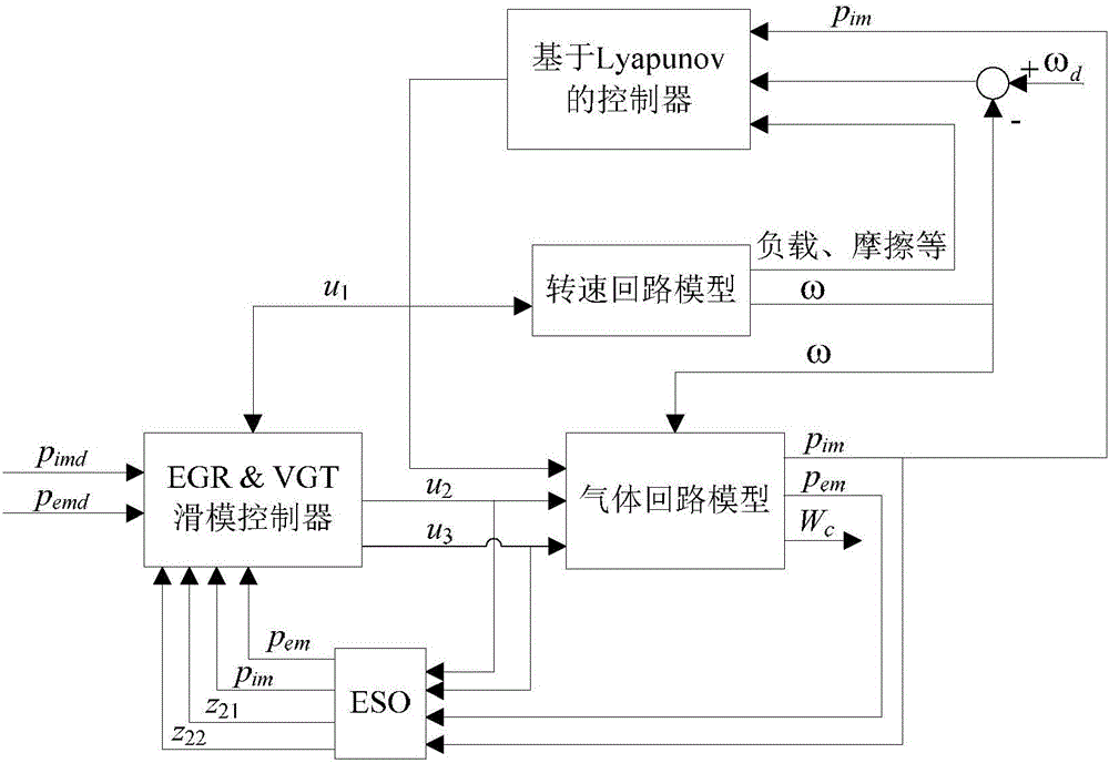
[0126] 3. Design the gas circuit controller. Design sliding mode controller parameters: λ=5, γ=150, gain β of state observer 11 = β 12 =5000,β 21 =900000,β 22 =500000.

[0127] The discontinuo...


PUM


Abstract

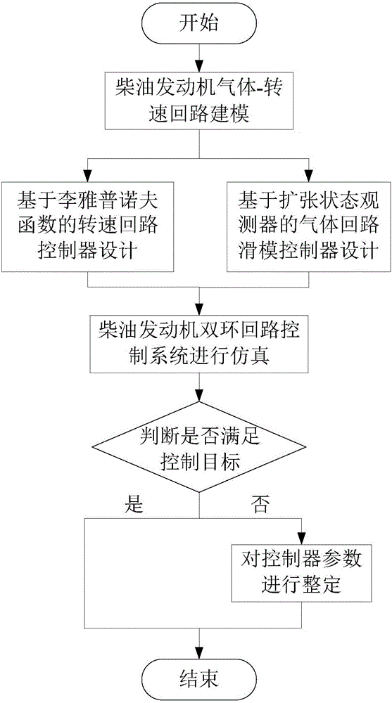
The invention provides an indirect energy-efficient emission reduction control method of a variable area turbocharged diesel engine. The basic idea of the present invention is to mathematically model gas and rotating speed loops of the diesel engine, determine control variables and design a controller for the model gas and rotating speed loops to achieve control objectives. Due to the existence of some unmodelled dynamics and external disturbances to a system during system modeling, an extended state observer is designed in the present invention for observing disturbances, and the disturbances are eliminated in the controller; simulation results indicate that a designed sliding mode controller based on the extended state observer has good tracking performance and disturbance restraint performance.

Description

technical field [0001] The invention relates to a control method of a control valve in a gas circuit and a rotational speed circuit of a turbocharged diesel engine with a variable cross-section, which is used for the exhaust emission control of the diesel engine and belongs to the field of automatic control research. Background technique [0002] Since the 20th century, the world's traditional fossil energy including coal and oil has been increasingly scarce, and the price of energy has been increasing. After the signing of the "Copenhagen Protocol" in 1992, countries began to adopt a series of effective measures to achieve energy conservation and emission reduction. [0003] Since the Industrial Revolution, CO 2 Emissions show a geometric base growth, and the transportation system, which accounts for 80% of its emissions, naturally undertakes the unshirkable task of reducing emissions. The internal combustion engine is currently the most widely used power engine system in...

Claims


Application Information

Patent Timeline
Patent Type & Authority Applications(China)
IPC IPC(8): F02B37/22F02M26/04F02D21/08
CPCF02B37/22F02D21/08F02D2021/083Y02T10/12
Inventor 梅振宇章伟郑文超赵锦焕蔡正义
Owner ZHEJIANG UNIV
Learn More