Gas phase opening liquid-inlet-prevention device

A gas-phase port and gas-phase pipe technology, applied in the field of gas-phase pipes, can solve the problems of large gas flow resistance, loud noise, pressure rise, etc., and achieve the effects of reducing gas outlet noise, increasing outlet area, and reducing gas outlet speed.

Active Publication Date: 2016-07-20
广东建成机械设备有限公司
View PDF5 Cites 0 Cited by
  • Summary
  • Abstract
  • Description
  • Claims
  • Application Information

AI Technical Summary

Problems solved by technology

When the transport vehicle is running, the liquid in the tank shakes and splashes, and the low-temperature liquid can easily flow into the gas-phase tube through the tank outlet of the gas-phase tube, and enter the pipeline outside the tank with a lower horizontal position. At this time, the low-temperature liquid will absorb the heat of the shell and Vaporization will cause the internal pressure of the tank to rise accordingly, which will affect the performance of the liquefied gas tank
Referring to a gas phase port liquid entry prevention device in Chinese Patent No. 200920291904.9, this patent discloses a gas phase port liquid entry prevention device, which includes a cup-shaped protective cover, and a gap for inserting a gas phase tube is provided on the upper part of the cup-shaped protective cover , the bottom and / or sidewall of the cup-shaped protective sleeve are provided with a plurality of ventilation holes, the total area of ​​the ventilation holes is not less than the radial cross-sectional area of ​​the gas phase tube, the positions of the ventilation holes of the outer sheath and the ventilation holes of the inner sheath It is arranged in a staggered state. This structure uses double cup-shaped protective sleeves. The protective sleeves are manufactured with multiple holes. The production process is complicated and the cost is high. In addition, the resistance to gas flow is large when used, and large noise is generated. There is a lot of room for improvement. Big

Method used


Image

  • Gas phase opening liquid-inlet-prevention device
  • Gas phase opening liquid-inlet-prevention device
  • Gas phase opening liquid-inlet-prevention device

Examples


Embodiment Construction

[0016] Embodiments of the present invention are described in detail below, examples of which are shown in the drawings, wherein the same or similar reference numerals designate the same or similar elements or elements having the same or similar functions throughout. The embodiments described below by referring to the figures are exemplary and are intended to explain the present invention and should not be construed as limiting the present invention.

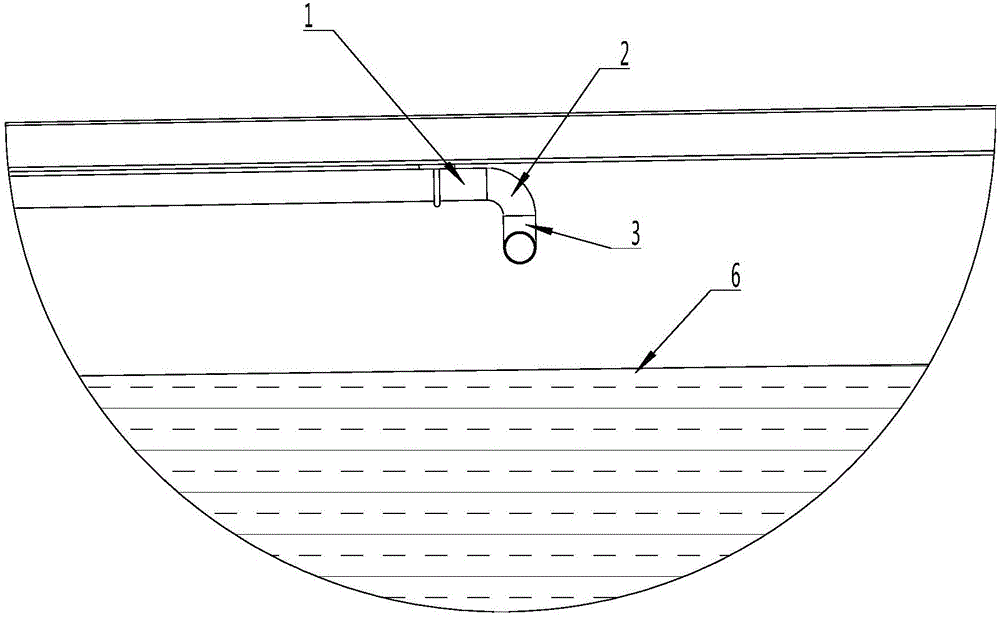
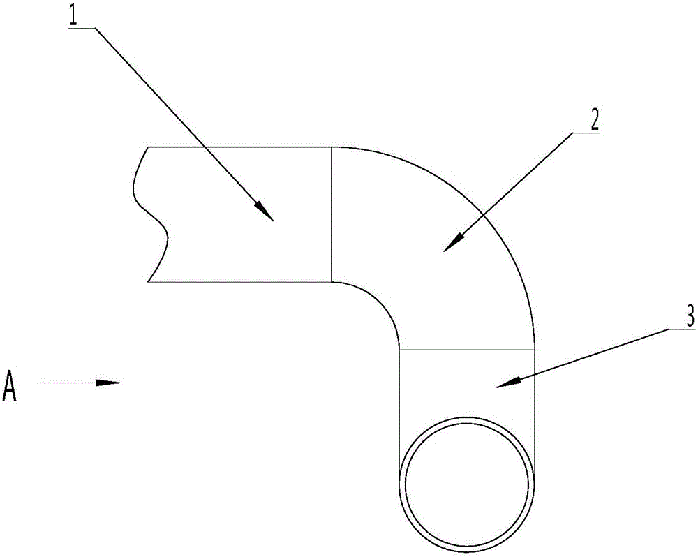
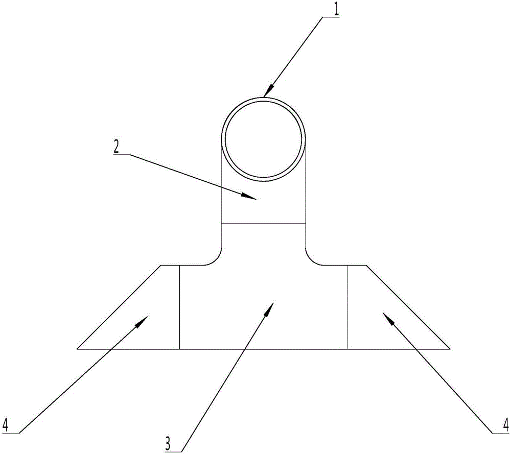
[0017] refer to Figure 1 to Figure 3 , the first embodiment of a device for preventing liquid entry at the gas phase port of the present invention, comprising a main pipe 2 connected to the gas phase pipe 1 and directed to the liquid surface 6, and a branch pipe 3 for separately guiding the gas, the other end of the main pipe 2 is connected to the branch pipe 3, the total radial cross-sectional area of ​​the outlet of the branch pipe 3 is not less than the radial cross-sectional area of ​​the gas phase pipe 1. Preferably, the b...


PUM


Abstract

The invention discloses a gas phase opening liquid-inlet-prevention device. The gas phase opening liquid-inlet-prevention device comprises a main pipe and a branch pipe, wherein the main pipe is connected with a gas phase pipe and points to the liquid level, and the branch pipe is used for carrying out separated guiding on gas; the main pipe is connected with the middle segment of the branch pipe, and the total radial cross-sectional area of an outlet of the branch pipe is not smaller than that of the gas phase pipe; and according to the gas phase opening liquid-inlet-prevention device, the effect on blocking liquid can be achieved, splashed liquid falls back into a tank, a gas path is separated through the branch pipe, the pipe area is increased, and the gas flow speed is reduced. According to the structure, resistance to the air flow can be further reduced, the noise in the use is reduced, it is ensured that gas can smoothly enter the device from the gas phase pipe, and therefore a pipeline outside the tank can be protected against being affected, and the service life of a tank car is prolonged.

Description

technical field [0001] The invention relates to a gas phase pipe of liquefied gas equipment, in particular to a device for preventing liquid from entering a gas phase port. Background technique [0002] A gas phase tube is usually installed inside the liquefied gas tank, and the gas phase stop valve is installed at the outer end of the gas phase tube at the bottom of the tank body, and the outlet at the inner end of the tank is located in the gas phase space on the top of the tank body, for gas to enter and exit the liquefied gas tank, forming a liquefied gas tank A pressure difference is generated between the storage tank and the liquid in the tank is convenient for loading and unloading. When the transport vehicle is running, the liquid in the tank shakes and splashes, and the low-temperature liquid can easily flow into the gas-phase tube through the tank outlet of the gas-phase tube, and enter the pipeline outside the tank with a lower horizontal position. At this time, t...

Claims


Application Information

Patent Timeline
IPC IPC(8): F17C13/00
CPCF17C13/00F17C2201/054F17C2221/033F17C2223/0161F17C2270/0171
Inventor 徐健池梁健灵孔庆勇梁健东吴永烈杨俊爵
Owner 广东建成机械设备有限公司
Why Eureka
Try Eureka