Air film cooling structure applied to turbine stationary blade

A film cooling and stationary blade technology, applied in the field of turbine blade cooling, can solve the problems of concentrated jet flow, weak coverage, and low utilization rate of jet cold air, and achieves increasing coverage width, reducing thermal stress, and reducing cold air consumption. Effect

Pending Publication Date: 2022-03-08
HARBIN ENG UNIV
View PDF0 Cites 0 Cited by
  • Summary
  • Abstract
  • Description
  • Claims
  • Application Information

AI Technical Summary

Problems solved by technology

Due to the disadvantages of concentrated jet flow, strong penetration, and weak coverage in traditional film cooling, the utilization rate of jet cooling air is low

Method used


Image

  • Air film cooling structure applied to turbine stationary blade
  • Air film cooling structure applied to turbine stationary blade
  • Air film cooling structure applied to turbine stationary blade

Examples


Embodiment Construction

[0021] The present invention will be further described below in conjunction with the accompanying drawings.

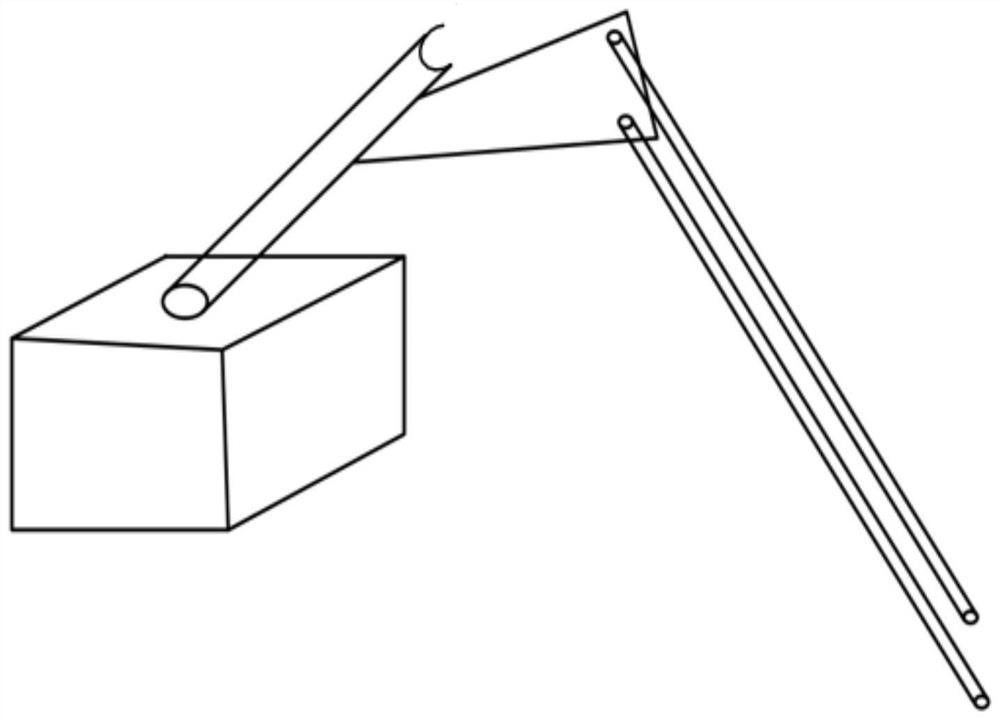
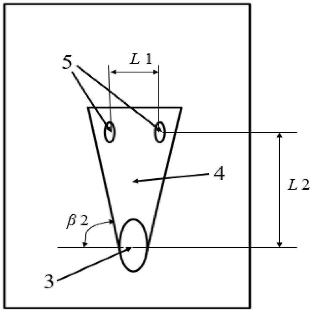
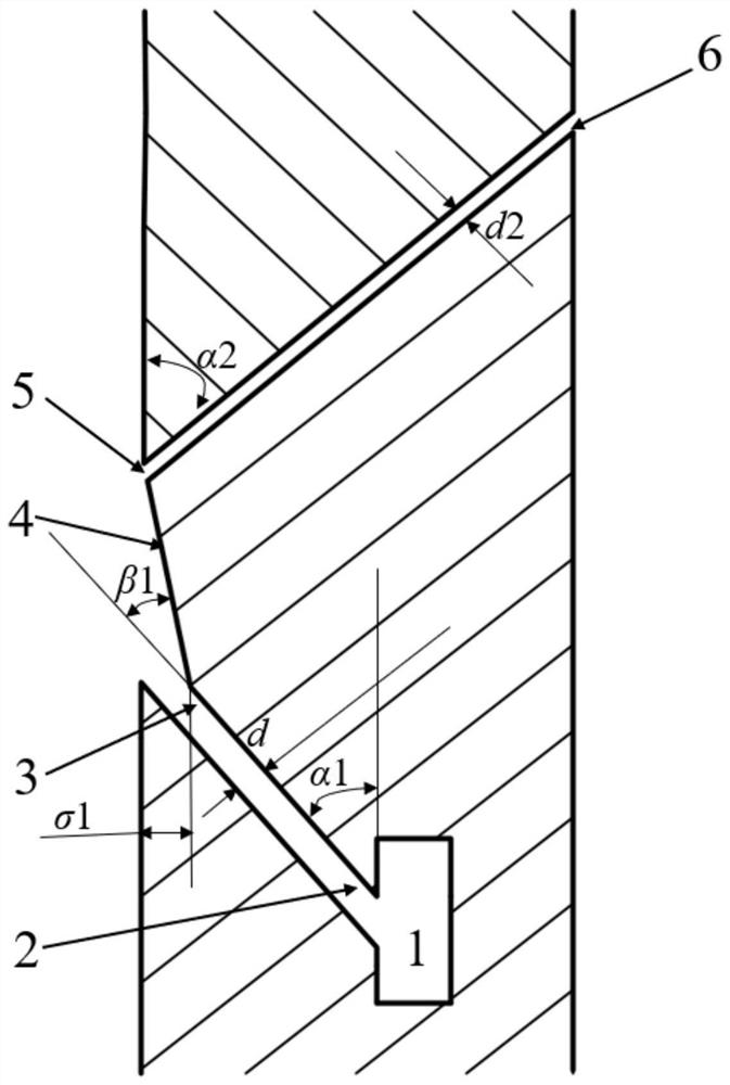
[0022] according to Figure 1 to Figure 4 , the present invention proposes a film cooling structure applied to turbine vanes, including a cold air cavity 1, a first group of cylindrical film cooling hole inlets 2, a first group of cylindrical film cooling hole outlets 3, and a blade surface The groove 4, the second group of air film hole inlets 5 run through the entire blade, and the second group of air film hole outlets 6.

[0023] The inlet 2 of the first group of cylindrical air film cooling holes is connected to the cold air chamber 1, the outlet 3 is fixed on the groove 4 on the surface of the blade, the groove 4 on the surface of the blade is fixed on the pressure surface of the blade, and the inlet 5 of the second group of cylindrical air film holes Fixed on the downstream part of the groove 4 on the surface of the blade, the second group of cylindrical air fil...


PUM


Abstract

The invention provides an air film cooling structure applied to a turbine stationary blade. The air film cooling structure comprises a cold air cavity, a first group of air film hole inlets, a first group of air film hole outlets, a blade surface groove, a second group of air film hole inlets and a second group of air film hole outlets. Inlets of the first set of cylindrical air film cooling holes are connected with a cold air cavity, outlets of the first set of cylindrical air film cooling holes are fixed to a blade surface groove, the blade surface groove is fixed to a blade pressure face, inlets of the second set of cylindrical air film cooling holes are fixed to the other end of the blade surface groove, and the second set of cylindrical air film cooling holes penetrate through the whole blade. And outlets of the second group of air film holes are fixed on the suction surface of the turbine stationary blade. The grooves are formed in the outlets of the first group of air film holes, the area of the outlets of the air film holes is increased, the cold air ejection speed is reduced, the second group of air film holes are adopted, air flow forms an air film after being ejected from the outlets of the second group of air film holes, cold air is reutilized, cold air consumption is reduced, and therefore the efficiency of the whole machine is improved.

Description

technical field [0001] The invention belongs to the technical field of turbine blade cooling, and in particular relates to an air film cooling structure applied to turbine stationary blades. Background technique [0002] According to the relevant principles of thermodynamics and the working principle of the gas turbine, increasing the initial temperature of the gas is a method that can significantly improve the power of the gas turbine and the efficiency of the whole machine. In recent years, the initial temperature of the gas in front of the blades of the first stage of the gas turbine has reached 2000K, which has far exceeded the heat resistance limit of general materials. For the safe operation of the gas turbine, various advanced high-temperature materials have been used to improve the temperature of the blades. The heat resistance of materials, such as directional crystallization, single crystal and other technologies, still cannot meet the operating temperature require...

Claims


Application Information

Patent Timeline
Patent Type & Authority Applications(China)
IPC IPC(8): F01D9/02F01D25/12
CPCF01D9/02F01D25/12
Inventor 姜玉廷陆松兵张昊苏徐超岳国强
Owner HARBIN ENG UNIV
Why Eureka
Try Eureka