Efficient battery material sintering furnace with push plate guide sliding function

A technology of guided sliding and battery materials, applied in the direction of furnaces, muffle furnaces, cooking furnaces, etc., can solve the problems of damage to the bottom wall of the furnace, cracks and collapse of the upper partition beam, and achieve side wall protection, good sliding performance, The effect of reducing the distance

Inactive Publication Date: 2016-07-20
SUZHOU HUIKE EQUIP CO LTD
View PDF6 Cites 1 Cited by
  • Summary
  • Abstract
  • Description
  • Claims
  • Application Information

AI Technical Summary

Problems solved by technology

Undoubtedly, compared with the single pusher single sagger, the double pusher four saggers and even the three pusher six saggers (three pairs of saggers superimposed) have the advantages of high production capacity and energy saving, but for each sintering area of ​​the furnace The difficulty of controlling the temperature and atmosphere increases accordingly, and the requirements for the upper partition beam also increase accordingly. Specifically: due to thermal expansion and contraction, the upper partition beam will appear cracks or even collapse, and cracks will lead to different sintering temperature regions. Temperature uniformity is affected, which ultimately leads to unsatisfactory sintering quality of battery materials
Therefore, in order to improve the sintering efficiency and reduce energy consumption in the prior art, it is the ultimate move to use double or triple push plates stacked with saggers, but the above-mentioned defects of the upper partition beam become a technical obstacle, because the upper partition is repaired too frequently. Partition beams will also affect the sintering efficiency of the sintering furnace and increase the inspection intensity of equipment management personnel and increase the maintenance cost of the sintering furnace
[0005] In addition, because the push plate in the prior art is directly placed on the bottom of the furnace, the bottom surface of the push plate is in full contact with the bottom wall of the furnace, so the friction between the push plate and the bottom wall of the furnace is relatively large, so on the one hand, due to the material The high power of the pushing device is not conducive to energy saving. On the other hand, it is easy to cause the push plate to rub to the point of damage, and even damage the bottom wall of the furnace and the two sides of the furnace due to the contact friction between the two sides of the push plate and the two sides of the furnace. wall
[0006] China Patent Authorization Announcement No. CN20293849U recommends "a sintering kiln for lithium battery positive electrode materials". This patent scheme gives the inspiration of the three-push plate and six sagger process, which has great advantages in reducing energy consumption per unit time and improving sintering efficiency. However, since the upper partition beam (confirmed from the patent drawing) is an integral arched structure, in addition to the lack of the function of guiding and sliding the push plate, there are also the aforementioned problems

Method used


Image

  • Efficient battery material sintering furnace with push plate guide sliding function
  • Efficient battery material sintering furnace with push plate guide sliding function
  • Efficient battery material sintering furnace with push plate guide sliding function

Examples


Embodiment

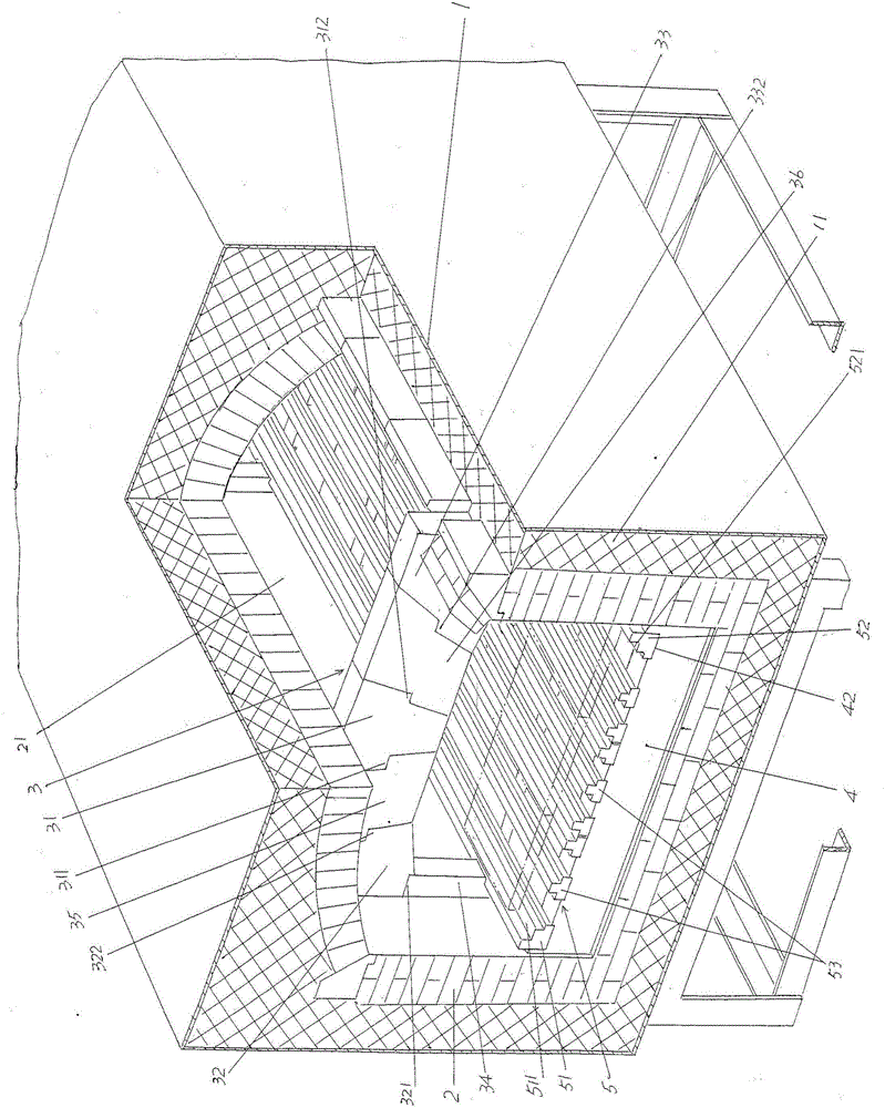
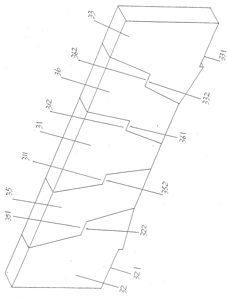
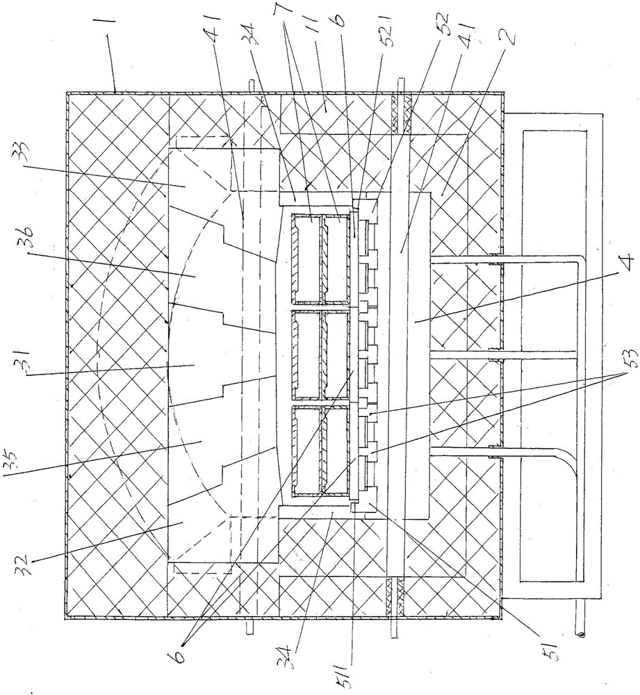
[0025] See figure 1 with figure 2 , shows the furnace shell 1, a furnace pad 11 is arranged around the inner wall of the furnace shell 1, shows a furnace lining 2, an upper partition beam 3 and a group of lower partition beams 4, and the furnace lining 2 surrounds the inner wall of the aforementioned furnace pad 11 It is arranged around (up, down, left, and right), and the space formed by the furnace lining 2 is formed as a furnace chamber 21. The upper partition beam 3 is arranged corresponding to the top of the furnace chamber 21 and is in contact with the top of the aforementioned furnace lining 2. A set of lower partition beams 4 are arranged at the bottom of the aforementioned furnace lining 2 in a spaced state.

[0026]As the technical points of the technical solution provided by the present invention: the structural system of the aforementioned high-efficiency sintering furnace for battery materials also includes a push plate guiding sliding mechanism 5, which include...


PUM


Abstract

An efficient battery material sintering furnace with a push plate guide sliding function comprises a furnace shell, a furnace lining, an upper partitioning beam and a lower partitioning beam, and is characterized by further comprising a push plate guide sliding mechanism, wherein the push plate guide sliding mechanism consists of a left limiting guide track, a right limiting guide track and a group of middle guide tracks; cross sections of the left limiting guide track and the right limiting guide track are L-shaped; cross sections of the group of middle guide tracks are inverted-T-shaped; a left limiting guide track groove is formed in one side, which faces the right limiting guide track, of the left limiting guide track; a right limiting guide track groove is formed in one side, which faces the left limiting guide track, of the right limiting guide track; a position, which corresponds to the left end of the lower partitioning beam, of the left limiting guide track is fixed with the lower partitioning beam; a position, which corresponds to the right end of the lower partitioning beam, of the right limiting guide track is fixed with the lower partitioning beam; the group of middle guide tracks are positioned between the left limiting guide track and the right limiting guide track and are fixed with the lower partitioning beam; the upper partitioning beam comprises a central insert block, a left insert block, a right insert block and a pair of insert block support columns. Collapse can be avoided; temperature control and atmosphere uniformized effects of adjacent sintering temperature regions are ensured; energy is saved; and a push plate and side walls of a furnace chamber are protected.

Description

technical field [0001] The invention belongs to the technical field of kiln facilities, and in particular relates to a high-efficiency sintering furnace for battery materials with the function of guiding and sliding a push plate. Background technique [0002] The aforementioned battery materials such as crystalline silicon photovoltaic cell materials, lithium battery positive electrode materials and so on. With the increasing social use of mobile electronic devices, the performance requirements for mobile electronic devices are also increasing. At the same time, the requirements for the production of components and materials related to mobile electronic devices are becoming increasingly stringent. Sintering furnaces for battery materials for mobile electronics place higher demands on them. Specifically, for example, the uniformity of particle size distribution, morphology and chemical index differences of the battery materials sintered by the sintering furnace will directly...

Claims


Application Information

Patent Timeline
Patent Type & Authority Applications(China)
IPC IPC(8): F27B5/00F27B5/06
CPCF27B5/00F27B5/06
Inventor 陈龙豪张文俊
Owner SUZHOU HUIKE EQUIP CO LTD
Why Eureka
Try Eureka