Magnetic Sensor Including Resistor Array Including A Plurality Of Resistive Element Sections

A technology of resistive elements and magnetic sensors, applied in the field of magnetic sensors, can solve the problems of reduced sensitivity of magnetic field detection and achieve the effect of improving output linearity

Active Publication Date: 2016-07-20
TDK CORPARATION
View PDF9 Cites 13 Cited by
  • Summary
  • Abstract
  • Description
  • Claims
  • Application Information

AI Technical Summary

Problems solved by technology

As a result, the magnetic field detection sensitivity is greatly reduced

Method used


Image

  • Magnetic Sensor Including Resistor Array Including A Plurality Of Resistive Element Sections
  • Magnetic Sensor Including Resistor Array Including A Plurality Of Resistive Element Sections
  • Magnetic Sensor Including Resistor Array Including A Plurality Of Resistive Element Sections

Examples


Embodiment Construction

[0026] Hereinafter, embodiments according to the present invention will be described with reference to the accompanying drawings.

[0027] In this specification, the magnetic sensor of the present invention will be described taking a configuration using a half-bridge circuit as an example. However, the configuration of the magnetic sensor is not limited thereto. The invention is also applicable to magnetic sensors using, for example, full bridge circuits.

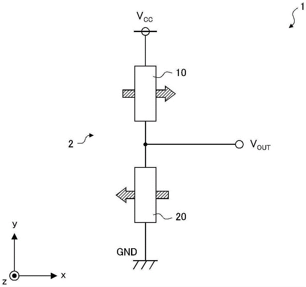
[0028] figure 1 is a diagram showing a circuit configuration of a magnetic sensor according to an embodiment of the present invention.

[0029] The magnetic sensor 1 of the present embodiment includes a half-bridge circuit 2 composed of a series circuit of a first resistor array 10 and a second resistor array 20 . In the half-bridge circuit 2 , one end of the first resistor array 10 and one end of the second resistor array 20 are connected to each other. In addition, the other end of the first resistor array 10 is conne...


PUM


Abstract

A magnetic sensor for detecting a component of an external magnetic field in a specific direction includes a resistor array including a plurality of resistive element sections each having a magnetoresistance element. Each of the plurality of resistive element sections has a different output characteristic curve with respect to the component of the external magnetic field in the specific direction.

Description

technical field [0001] The present invention relates to a magnetic sensor using a magnetoresistive element, and more particularly, to a magnetic sensor including a resistive array including a plurality of resistive element sections each having a magnetoresistive element. Background technique [0002] In recent years, magnetic sensors using magnetoresistive (MR) elements have been used as sensors for detecting the position of a movable body (see, for example, JP63-274817A, JP04-160315A, JP08-285509A, and JP09-016923A). [0003] Each of the disclosed magnetic sensors is configured such that the output of the magnetic sensor varies according to a change in the relative position of the movable body with respect to the magnetic sensor, for example, when a specific directional component of an external magnetic field generated by a magnet disposed in the movable body changes. Change. Thus, a specific directional component of the external magnetic field is detected, whereby the pos...

Claims


Application Information

Patent Timeline
Patent Type & Authority Applications(China)
IPC IPC(8): G01B7/00
CPCG01B7/003G01R33/093G01R33/098H10N50/10H10B61/00H10N50/80
Inventor 须藤俊英平林启
Owner TDK CORPARATION
Why Eureka
Try Eureka