Semiconductor device and power converter using it

a technology of electromagnetic field and power converter, which is applied in the direction of diodes, electronic switching, pulse techniques, etc., can solve the problems of large current loss, large forward voltage, cost reduction of inverter and converter, etc., and achieve small loss, low cost, and low forward voltage of flywheel diodes.

Active Publication Date: 2011-03-31
HITACHI LTD
View PDF6 Cites 11 Cited by
  • Summary
  • Abstract
  • Description
  • Claims
  • Application Information

AI Technical Summary

Benefits of technology

[0009]According to this invention, it is intended that the tradeoff relation between reduction in forward voltage drop and reduction in backward recovery current the conventional flywheel diode fails to achieve can drastically be improved to decrease the flywheel diode conduction loss and switching loss at a time and besides the bounce voltage can be suppressed to a great extent by making small the current change rate di / dt of backward recovery current.
[0026]According to the present invention, by providing the flywheel diode with a novel device which switches over from the pn diode to the Schottky diode or vice-versa, current can be passed through the pn diode of small forward voltage when the current flows forwardly and backward recovery can be performed during backward recovery through the Schottky diode of small backward recovery current, with the result that the forward voltage of the flywheel diode can be reduced and the backward recovery loss can be decreased and therefore, a semiconductor device of drastically small loss and a power converter using it can be provided. Then, since the backward recovery current can be reduced and its current change rate di / dt can be rendered very small, a semiconductor device in which bounce voltage generated cooperatively with a parasitic inductance can also be decreased to a great extent and a power converter using it can be provided.

Problems solved by technology

But for silicon diode, the forward voltage is very large and the loss increases in the inverter handling large currents.
However, this type of Schottky diode is disadvantageous in that its crystalline quality is bad, its fabrication process is difficult and its increase in diameter size is inferior to that using silicon, resulting in high costs leading to prevention of cost reduction of the inverter and converter, and therefore it comes into limited use.
In the diode shown in FIG. 20, however, there arise problems that further injection of electric charges to reduce the forward voltage drop degrades the backward recovery characteristics and conversely, the suppression of electric charge injection aiming at improvements in the backward recovery characteristics increases the forward voltage accompanied by an increase in loss, making it difficult for the conventional structure to further improve the characteristics of the flywheel diode.

Method used


Image

  • Semiconductor device and power converter using it
  • Semiconductor device and power converter using it
  • Semiconductor device and power converter using it

Examples


Embodiment Construction

[0048]Embodiments of the present invention will now be described with reference to the accompanying drawings.

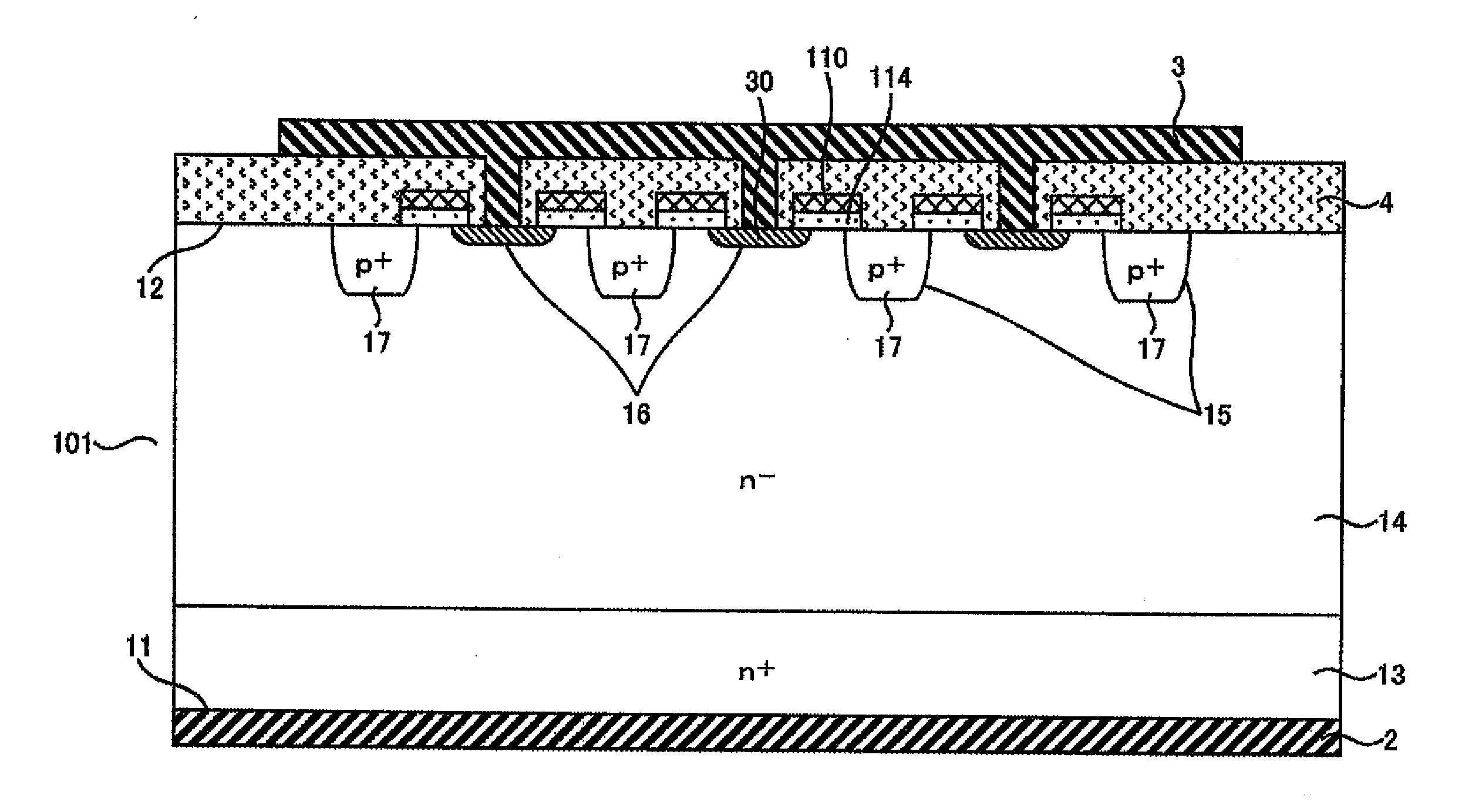
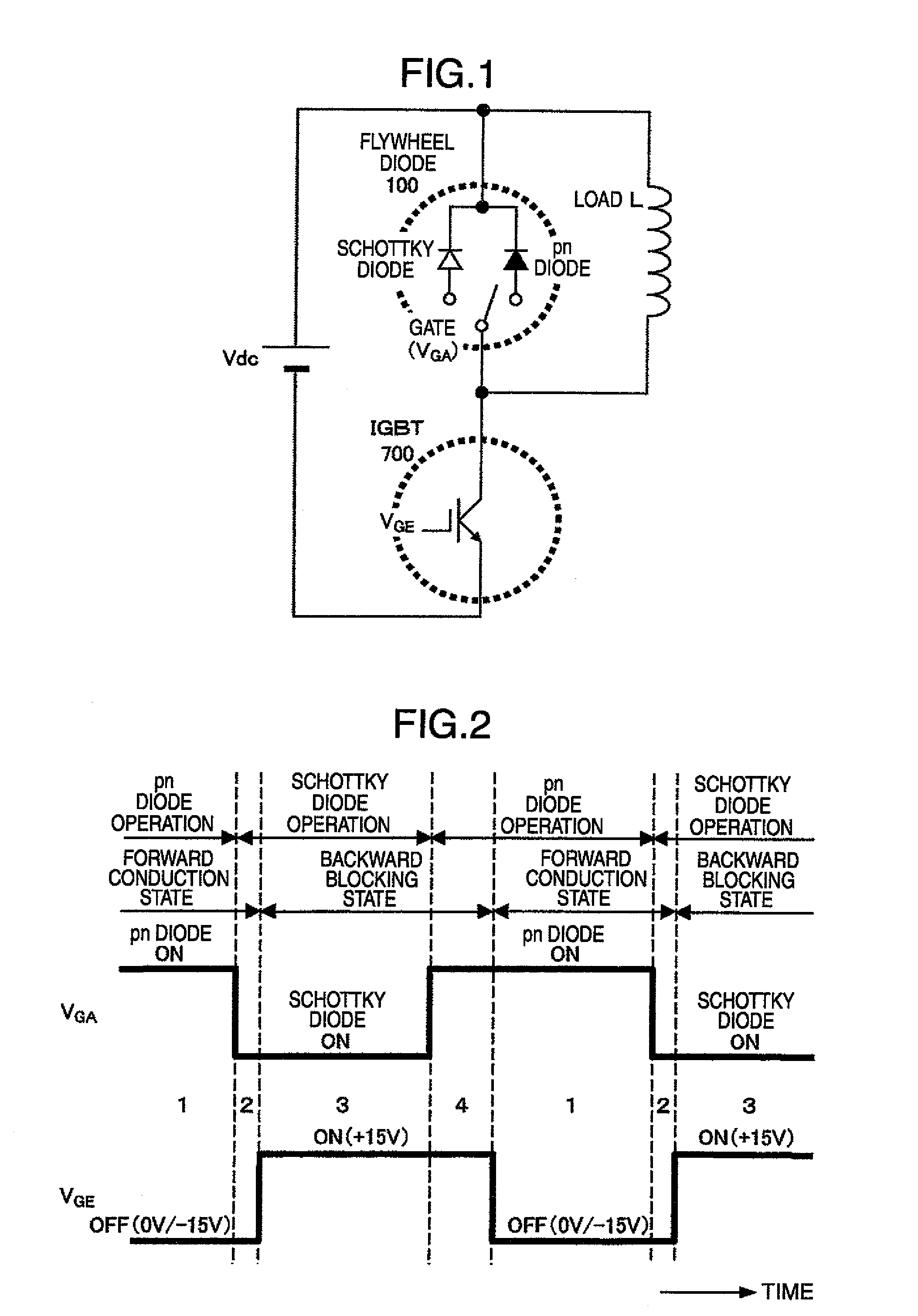
[0049]Referring first to FIG. 1, an example of a semiconductor device to which the present invention is applied and a power converter using the same is illustrated in schematic circuit diagram form. In connection with FIG. 1, the power converter will be described as having paired upper and lower arms. Advantageously, in the present invention, a flywheel diode 100 is functionally separated to act as either a pn diode or a Schottky diode and has a gate for selection of the separate functions. This kind of diode will be termed hereunder a gate controlled diode. The gate controlled diode 100 can operate as the pn diode during conduction and can impersonate the Schottky diode during backward recovery, making full use of advantages of the both types, so that reduction in conduction loss and backward recovery loss and suppression of bounce voltage as well can be realized and drastic...


PUM


Abstract

A semiconductor device and a power converter using it wherein a switching power device and a flywheel diode are connected in series, the flywheel diode includes a region having a Schottky junction to operate as a Schottky diode and a region having a pn junction to operate as a pn diode and control operation is performed such that when current flows forwardly through the flywheel diode, the pn diode operates and when the flywheel diode recovers backwardly, the Schottky diode operates mainly.

Description

BACKGROUND OF THE INVENTION[0001]The present invention relates to a semiconductor device and a power converter using it and more particularly, to a semiconductor device of the type having flywheel diodes and a power converter using the same.[0002]In recent years, many kinds of inverters and converters have been used in electric power converters dedicated to energy saving and renewable energy technologies. For realization of Low-carbon society, drastic spread of the power converters is still indispensable. FIG. 19 shows an example of an inverter for controlling a motor 950 in variable speed and realizing energy saving. Electric energy from a DC power supply Vcc is converted into an alternating current at a desired frequency through the use of IGBT's (Insulated Gate Bipolar Transistors) 700, that is, a kind of power semiconductors, in order to change the revolution speed of the motor 950. The motor 950 is a three-phase motor having an input 910 of U-phase, an input 911 of V-phase and ...

Claims


Application Information

Patent Timeline
Patent Type & Authority Applications(United States)
IPC IPC(8): H01L27/06
CPCH01L27/0664H01L29/7395H01L29/7391H03K17/164H03K17/168H03K17/74H03K2217/0036
Inventor MORI, MUTSUHIRO
Owner HITACHI LTD
Why Eureka
Try Eureka