Optical pickup device

a technology of optical pickup and phase change, which is applied in the field of optical pickup devices, can solve the problem achieve the effect of small phase change ra

Inactive Publication Date: 2005-08-30
SHARP KK
View PDF9 Cites 11 Cited by
  • Summary
  • Abstract
  • Description
  • Claims
  • Application Information

AI Technical Summary

Benefits of technology

[0017]With this arrangement, even if the center of the objective lens is not aligned with the center of the aberration correcting optical system, the rate of change in the slope of the phase is small because a magnitude of a phase monotonously changes. Therefore, the center misalignment does not cause a large aberration if the objective lens and the aberration correcting optical system have been appropriately adjusted in a state having no center misalignment.
[0039]With this arrangement, it is possible to easily realize the foregoing arrangement by applying a voltage to the central electrode and one or more circular electrodes so that the electrodes respectively have predetermined voltages.

Problems solved by technology

With this arrangement, even if the center of the objective lens is not aligned with the center of the aberration correcting optical system, the rate of change in the slope of the phase is small because a magnitude of a phase monotonously changes.

Method used


Image

  • Optical pickup device
  • Optical pickup device
  • Optical pickup device

Examples


Embodiment Construction

[0052]The following will explain an embodiment of the present invention with reference to attached drawings.

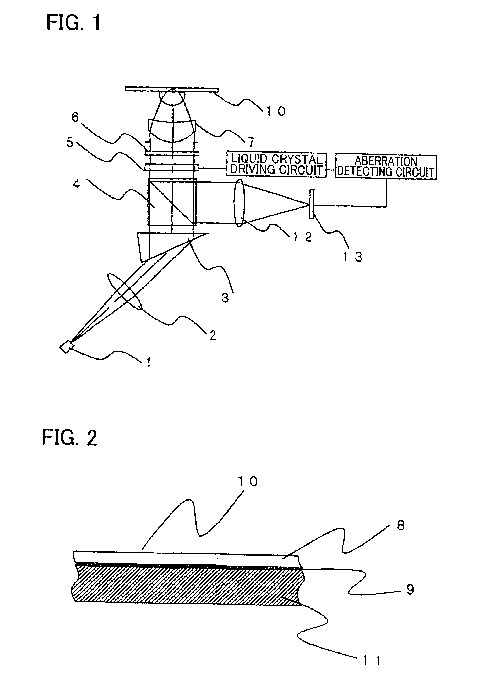
[0053]As shown in FIG. 1, an optical pickup device of the present embodiment is so arranged that linearly polarized laser beam emitted from an LD (Laser Diode) 1 is converted into a parallel ray at a collimator lens 2 and enters a shaping prism 3. The shaping prism 3 shapes an elliptical intensity distribution of the laser beam emitted from the LD 1 so that the intensity distribution has an approximately circular shape.

[0054]After this, the light exiting from the shaping prism 3 passes through a polarizing bean splitter 4, and enters an aberration correcting optical system 5. Then, the light is converted into circularly polarized light at a quarter-wave plate 6. The ray of light that is converted into circularly polarized light by the quarter-wave plate 6 is deflected by a 45-degree mirror (not shown), and an objective lens 7 focuses the light onto an optical recording medium ...


PUM

PropertyMeasurementUnit
thicknessaaaaaaaaaa
thicknessaaaaaaaaaa
thicknessaaaaaaaaaa

Abstract

An optical pickup device which includes (A) a light source, and (B) an objective lens and an aberration correcting optical system which are located in a light path from the light source to an optical recording medium is so arranged that the aberration correcting optical system imparts a phase distribution to luminous flux which transmits the aberration correcting optical system, so as to correct a predetermined aberration; and an amount of phase of the aberration correcting optical system when correcting the aberration is set in such a manner that the aberration correcting optical system imparts a larger amount of phase at a position farther from a point where the aberration correcting optical system crosses an optical axis of light emitted from the light source. With this, it is possible to increase a tolerance for the center misalignment of the objective lens so as to reduce aberration caused by the center misalignment.

Description

[0001]This application claims priority pursuant to 35 USC 371 from PCT international application No. PCT / JP02 / 08265 filed Aug. 13, 2002, which in turn claims priority from Japanese application No. 2001-253735 filed Aug. 24, 2001, the disclosures of which are incorporated herein by reference.TECHNICAL FIELD[0002]The present invention relates to optical pickup devices for recording and reproducing information on and from an optical information recording medium.BACKGROUND ART[0003]Optical technology has many characteristics such as capability of high-speed processing at a frequency of light (speed is high because of high frequency), capability of spatial information processing, and capability of phase processing. For this reason, the optical technology has been researched, developed, and put into practical use in a wide range of fields such as communications, measurement, and processing.[0004]Such optical technology uses a high-precision objective lens to focus a light beam.[0005]In ac...

Claims


Application Information

Patent Timeline
Patent Type & Authority Patents(United States)
IPC IPC(8): G11B7/125G11B7/135G11B7/1369
CPCG11B7/1356G11B7/1359G11B7/1369G11B7/13927
Inventor KITAMURA, KAZUYAKURATA, YUKIOIWAKI, TETSUO
Owner SHARP KK
Why Eureka
Try Eureka