
Detecting method for residual stress of steel structure

A residual stress, steel structure technology, applied in the direction of measuring force, measuring device, instrument, etc., can solve the problems of lack of normative regulations, insufficient research, and no obvious improvement of measurement accuracy, to reduce the depth, facilitate operation, Reduce the effect of damage

Active Publication Date: 2016-07-20
HANGZHOU HUAXIN TESTING ENG CO LTD
View PDF5 Cites 11 Cited by
  • Summary
  • Abstract
  • Description
  • Claims
  • Application Information

AI Technical Summary

Problems solved by technology

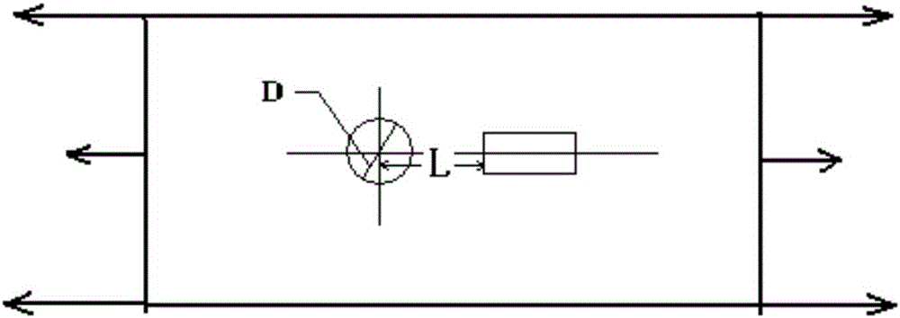
[0006] Although the drilling method has been developed relatively maturely at present, it has the advantages of high precision, simple operation, and low cost, but these years, it has only stayed in the traditional operation, without major technological breakthroughs, and the measurement accuracy is not obvious. The improvement of the research is not deep enough. There are no specifications for the diameter and depth of the borehole, the number and distribution of the borehole, and the positional relationship between the strain gauge and the borehole. When measuring, it is only based on the experience of the surveyor. get more precise requirements

Method used


Image

  • Detecting method for residual stress of steel structure
  • Detecting method for residual stress of steel structure
  • Detecting method for residual stress of steel structure

Examples


Embodiment approach 1

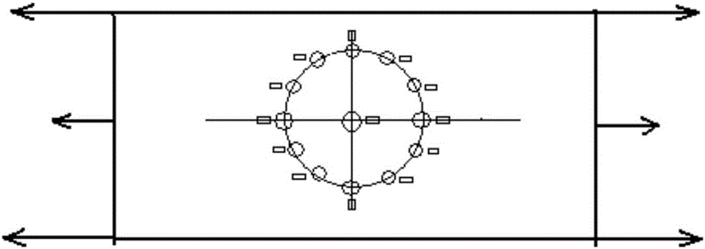
[0036] Embodiment 1: The size of the selected test member is: length A=0.08m, width B=0.05m, thickness 0.08m, hole diameter D=2.5mm, hole depth L=27.5mm, hole inclination angle of 35 degrees, strain gauge The distance from the hole is H=2mm, the modulus of elasticity is E=350GPa, the load is 2MPa and the average distribution force is applied, the number of holes is 13, the value of each hole is measured five times, the average value is taken, and the reverse side is used for simultaneous measurement, specifically as follows figure 2 As shown, the results measured three times were 52.33MPa, 56.25MPa and 53.12MPa respectively, and finally the average value was obtained to obtain 53.90MPa.

Embodiment approach 2

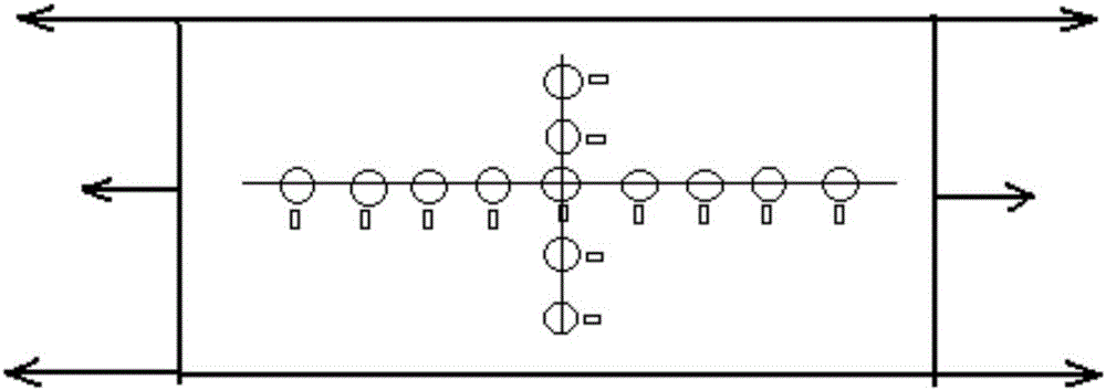
[0037]Embodiment 2: The size of the selected test member is: length A=0.10m, width B=0.04m, thickness 0.08m, hole diameter D=2.0mm, hole depth L=22.0mm, each hole is distributed as a cross, and the distance between the strain gauges Hole distance H = 2mm, elastic modulus E = 350GPa, load 2MPa average distribution force, the number of holes is 13, the value of each hole is measured five times, take the average value, and use the positive and negative sides to measure at the same time, specifically as follows image 3 As shown, the results measured three times are 65.23MPa, 67.25MPa and 66.14MPa respectively, and finally the average value is obtained to get 66.21MPa.

[0038] On the basis of the existing technology, the present invention further optimizes the requirements of specific parameters in the measurement of steel structure residual stress through a large number of experimental studies, by accurately setting the diameter of the borehole, the depth of the borehole, and the...


PUM

PropertyMeasurementUnit
Lengthaaaaaaaaaa
Widthaaaaaaaaaa
Thicknessaaaaaaaaaa

Abstract

The invention provides a detecting method for residual stress of a steel structure. Furthermore improvement is realized based on an original hole drilling method. Specific parameters in residual stress of the steel structure are further optimized. Through accurately setting parameters such as hole diameter, hole depth, hole distribution condition, hole inclination angle and distance between holes and a strain gauge, more accurate testing structure is realized. Particularly through researching the inclination angle of each hole, a defect of drilling only vertical holes in traditional technology is overcome. Through drilling oblique holes which incline in an angle range, stress change at the periphery of the drilling hole can be more accurately acquired. Furthermore hole depth is increased as possible. Depth in the vertical direction is reduced. Damage of a tested component is reduced.

Description

technical field [0001] The invention relates to a method for detecting residual stress and strain in a steel structure, specifically a method for detecting residual stress and strain in a steel structure by using a drilling method, which has more advantages compared with the existing drilling method in the prior art Precise, simple and easy features. Background technique [0002] With the development of modern building structure technology, steel structures are used more and more frequently in buildings, and the design requirements for steel structures are also getting higher and higher, and various forms of steel structure projects have emerged. In engineering, the residual stress of the component and the external force during the use of the component interact and superimpose, so the residual stress has a great influence on the strength, fatigue performance and service life of the structure. The existence of residual stress, on the one hand, will reduce the strength of the...

Claims


Application Information

Patent Timeline
IPC IPC(8): G01L1/20
CPCG01L1/205
Inventor 郑刚兵黄友鹏周超王力子
Owner HANGZHOU HUAXIN TESTING ENG CO LTD
Learn More