A detection system and detection method for power generation equipment

A technology of power generation equipment and detection system, which is applied in the monitoring of photovoltaic systems, photovoltaic power generation, and measurement of electricity, etc., can solve the problems of inability to accurately reflect the working characteristics of power generation equipment and inaccurate detection results of power generation equipment.

Active Publication Date: 2019-05-10
ELECTRIC POWER RESEARCH INSTITUTE, CHINA SOUTHERN POWER GRID CO LTD
View PDF5 Cites 0 Cited by
  • Summary
  • Abstract
  • Description
  • Claims
  • Application Information

AI Technical Summary

Problems solved by technology

However, the inventors of the present application found that in the hybrid simulation technology, when simulating the various structures in the power generation equipment, the high power and high voltage of the actual power grid were processed to a certain extent to convert them into low power and low voltage , and then carry out the corresponding detection, which makes the detection results of the power generation equipment inaccurate and cannot accurately reflect the working characteristics of the power generation equipment

Method used


Image

  • A detection system and detection method for power generation equipment

Examples


Embodiment 1

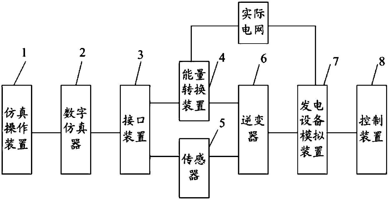
[0035] An embodiment of the present invention provides a power generation equipment detection system, specifically, such as figure 1 As shown, the detection system for power generation equipment includes: a simulation operation device 1 , a digital simulator 2 , an interface device 3 , an energy conversion device 4 , a sensor 5 , an inverter 6 and a power generation device simulation device 7 . The power generation equipment detection system can be used to detect new energy power generation equipment.

[0036] The specific connection methods of the above structures are as follows: the simulation operation device 1 is connected with the digital simulator 2; the digital simulator 2 is connected with the simulation operation device 1 and the interface device 3; the interface device 3 is connected with the digital simulator 2, the energy conversion device 4 and the sensor 5 connection; the energy conversion device 4 is connected with the interface device 3, the inverter 6 and the ...

Embodiment 2

[0042] An embodiment of the present invention provides a power generation equipment detection method, which is used in the power generation equipment detection system described in Embodiment 1. Specifically, the power generation system detection method includes:

[0043] The simulation operation device establishes a digital simulation model of the power grid, sets the test sequence of a plurality of test modules included in the digital simulation model of the power grid, and outputs the digital simulation model of the power grid to the digital simulator.

[0044] The digital simulator runs the grid digital simulation model received from the simulation operation device, and outputs the analog voltage to the interface device.

[0045] The interface device performs digital-to-analog conversion on the analog voltage.

[0046] The generating equipment simulation device obtains the second power from the actual grid, the second power is the total power of the actual grid, and outputs...


PUM


Abstract

The invention discloses a power generating equipment testing system and a power generating equipment testing method, wherein the power generating equipment testing system and the power generating equipment testing method relate to the field of power generation technology. The power generating equipment testing system and the power generating equipment testing method settle technical problems of inaccurate testing result on the power generating equipment and incapability of accurately reflecting operation characteristics of the power generating equipment. The power generating equipment testing system comprises a simulation operation device, a digital simulator, an interface device, an energy conversion device, a sensor, an inverter and a power generating equipment simulating device. The power generating equipment testing system and the power generating equipment testing method are used for testing the power generating equipment.

Description

technical field [0001] The invention relates to the technical field of power generation, in particular to a detection system and detection method for power generation equipment. Background technique [0002] With the development of society and economy, the requirements for the power system are getting higher and higher. In order to ensure the performance of the power system, it is necessary to detect the working characteristics of the power generation equipment in the power system. At present, the working characteristics of power generation equipment are mainly tested through hybrid simulation technology. However, the inventors of the present application found that in the hybrid simulation technology, when simulating the various structures in the power generation equipment, the high power and high voltage of the actual power grid were processed to a certain extent to convert them into low power and low voltage , and then carry out the corresponding detection, which makes th...

Claims


Application Information

Patent Timeline
Patent Type & Authority Patents(China)
IPC IPC(8): G01R31/00H02S50/10
CPCG01R31/00H02S50/10Y02E10/50
Inventor 蔡海青郭琦郭海平张建设伍文聪黄立滨
Owner ELECTRIC POWER RESEARCH INSTITUTE, CHINA SOUTHERN POWER GRID CO LTD
Why Eureka
Try Eureka