Radiation prevention transformer capable of remote monitoring

A remote monitoring and transformer technology, applied in the field of transformers, can solve the problems of reducing the work efficiency of staff, the influence of transformer radiation, and the inability to monitor transformers remotely, so as to improve the effect of radiation protection and work efficiency

Active Publication Date: 2016-07-20
PENGLAI POWER SUPPLY CO OF STATE GRID SHANDONG ELECTRIC POWER CO
View PDF7 Cites 1 Cited by
  • Summary
  • Abstract
  • Description
  • Claims
  • Application Information

AI Technical Summary

Problems solved by technology

Although this invention can reduce radiation to a certain extent, it still cannot solve the problem of the large impact of

Method used


Image

  • Radiation prevention transformer capable of remote monitoring
  • Radiation prevention transformer capable of remote monitoring

Examples


Example Embodiment

[0018] Example 1

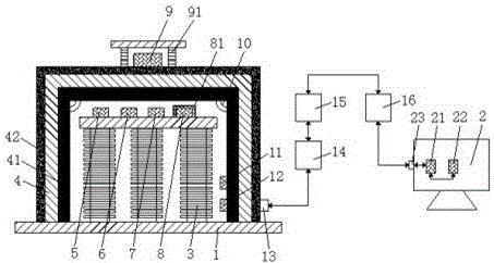
[0019] see figure 1 , the present invention provides a kind of technical scheme:

[0020] A radiation protection transformer that can be remotely monitored includes a base 1 and a remote control terminal 2, a transformer assembly 3 is mounted on the upper surface of the base 1, a steel plate casing 4 is fixedly sleeved on the outer side of the transformer assembly 3, and the inner surface of the casing 4 is fixed and tightly attached There is a lead plate 41, the outer surface of the casing 4 is coated with an anti-radiation coating 42, through the steel plate casing 4 provided on the outside of the transformer assembly 3 and the lead plate 41 arranged on the inner side of the steel plate casing 4 and the outer surface of the steel plate casing 4. The radiation protection coating 42 can reduce radiation and improve the radiation protection effect. The temperature sensor 5, the voltage detection unit 6, the central processing unit 7, the memory 8, the filter...

Example Embodiment

[0023] Embodiment 2

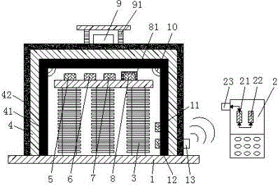
[0024] see figure 2 , this embodiment provides a technical solution:

[0025] A radiation protection transformer that can be remotely monitored includes a base 1 and a remote control terminal 2, a transformer assembly 3 is mounted on the upper surface of the base 1, a steel plate casing 4 is fixedly sleeved on the outer side of the transformer assembly 3, and the inner surface of the casing 4 is fixed and tightly attached There is a lead plate 41, the outer surface of the casing 4 is coated with an anti-radiation coating 42, through the steel plate casing 4 provided on the outside of the transformer assembly 3 and the lead plate 41 arranged on the inner side of the steel plate casing 4 and the outer surface of the steel plate casing 4. The radiation protection coating 42 can reduce radiation and improve the radiation protection effect. The temperature sensor 5, the voltage detection unit 6, the central processing unit 7, the memory 8, the filter 11 and ...


PUM


Abstract

The invention discloses a radiation prevention transformer capable of remote monitoring. The radiation prevention transformer comprises a base and a remote control terminal, wherein a transformer assembly is arranged on the upper surface of the base, a steel plate shell fixedly sleeves the outer side of the transformer assembly, a lead plate is fixedly in close contact with the surface of the inner side of the shell, a temperature sensor, a voltage detection unit, a central processing unit, a storage device, a filter and a first signal amplifier are arranged inside the transformer assembly, and a radiation detection unit is arranged on the surface of the outer side of the steel plate shell. By the radiation prevention transformer capable of remote monitoring, radiation is prevented, the radiation prevention effect is improved, the real-time working condition of the transformer assembly is sent to the remote control terminal, a user is convenient to remotely monitor the working condition of the transformer, the transformer can be processed at the first time when a fault occurs, and the working efficiency of a worker is improved.

Description

technical field [0001] The invention relates to the technical field of transformers, in particular to a radiation protection transformer that can be remotely monitored. Background technique [0002] Transformer is a device that uses the principle of electromagnetic induction to change the AC voltage. The main components are the primary coil, the secondary coil and the iron core (magnetic core). The main functions are: voltage transformation, current transformation, impedance transformation, isolation, voltage regulation (magnetic saturation transformer), etc. Transformers are everywhere in our lives and work. [0003] The Chinese Patent Application Publication No. CN103151140A discloses a radiation protection transformer, which belongs to the technical field of transformer equipment. The utility model comprises a transformer casing, which is characterized in that the transformer casing is provided with a transformer component, the outside of the transformer casing is provi...

Claims


Application Information

Patent Timeline
IPC IPC(8): H01F27/02H01F27/36H01F27/40
CPCH01F27/02H01F27/36H01F27/40H01F27/402H01F2027/406
Inventor 王德毅季翠娜王志凤杨振东张刚纪广欣吴新鹏李长磊王德刚荆永梅张夕军刘斌李树臣葛祖郁张军苗
Owner PENGLAI POWER SUPPLY CO OF STATE GRID SHANDONG ELECTRIC POWER CO
Why Eureka
Try Eureka