
Self-protection module type communication base station monitoring device

A technology for monitoring devices and communication base stations, applied in the direction of selection devices, electrical components, etc., can solve the problems of being vulnerable to lightning strikes, burning out the electrical equipment of the base station, and increasing the cost of the project, so as to reduce costs and installation difficulties, and save installation time , Reduce the effect of maintenance workers

Inactive Publication Date: 2016-07-20
丹东华通测控有限公司
View PDF0 Cites 0 Cited by
  • Summary
  • Abstract
  • Description
  • Claims
  • Application Information

AI Technical Summary

Problems solved by technology

[0004] 1. Due to the lack of specific monitoring methods, it is difficult to manage the power consumption of the base station, and it is impossible to monitor and manage the power consumption of the base station scientifically and systematically
Commonly used measuring electric meters can only measure the usage of a single electric load. When there are multiple electric loads to be measured, an equal number of electric meters need to be installed, which increases the workload of installation and construction and increases the cost of the entire project.
[0005] 2. Most of the communication base stations are located in mountainous areas or on a higher ground level, and this environment is vulnerable to lightning strikes during thunderstorms, thus burning out the relatively fragile electrical equipment in the base station
[0006] 3. In old communication base stations, the wires are overloaded for a long time, and the temperature of the cables will continue to rise, which may even cause the insulation layer of the wires to burn, causing a fire
[0007] 4. When the communication base station fails, it will seriously affect the normal operation of the equipment in the base station. If it cannot be found and repaired in time, the base station equipment may be shut down, resulting in communication failure or even damage to the equipment, resulting in serious losses.
However, manual monitoring may not be able to detect the above faults in time

Method used


Image

  • Self-protection module type communication base station monitoring device
  • Self-protection module type communication base station monitoring device

Examples


Embodiment Construction

[0017] Combined with the accompanying drawings figure 1 And embodiment the present invention is described in further detail.

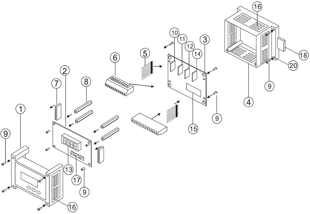
[0018] A self-protection modular communication base station monitoring device, the monitoring device mainly includes an upper case 1, a circuit board 2, a power board 3, and a bottom case 4 which are sequentially connected together;

[0019] The screw 9 on the upper case 1 passes through the circuit board 2 and is screwed with the copper column 8 to connect the upper case 1 and the circuit board 2;

[0020] The circuit board 2 is integrated with the connection through the pin 5, the terminal 6, the socket 7 and the copper column 8;

[0021] The circuit board 2 and the power supply board 3 are combined and placed in the bottom case 4;

[0022] Combine the upper case 1 and the bottom case 4 together.

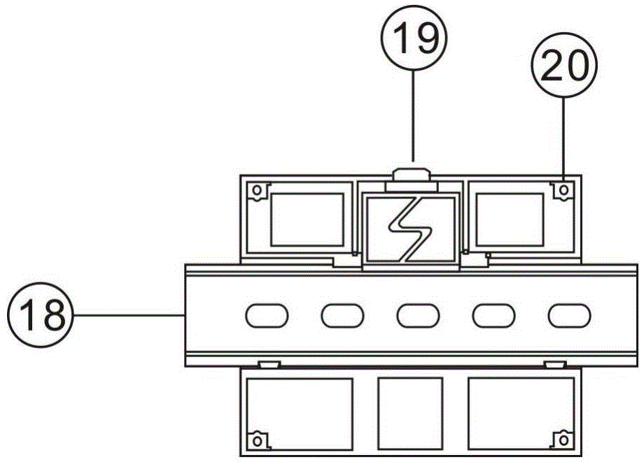
[0023] The back of the bottom case 4 is provided with guide rails 18 , and the back is provided with corresponding guide rails 18 and provided with lug...


PUM


Abstract

The invention discloses a self-protection module type communication base station monitoring device. The monitoring device mainly comprises an upper shell, a circuit board, a power supply board and a bottom shell which are successively connected. The screws on the upper shell penetrate the circuit board and then are screwed with copper posts, thus fixedly connecting the upper shell and the circuit board. The circuit board and the power supply board are connected integrally through pins, terminals, a socket and the copper posts. The circuit board and the power supply board are combined integrally and then are contained in the bottom shell. The upper shell and the bottom shell are combined together. According to the device, the cost and the mounting difficulty are reduced, the mounting time is saved, the maintenance work to the monitoring device is reduced, different use demands of the power supply of a communication base station are satisfied, and the universality is high.

Description

technical field [0001] The invention relates to the technical field of communication equipment, in particular to a self-protection modular communication base station monitoring device. Background technique [0002] At present, the phenomenon of power energy shortage is becoming more and more prominent, and energy saving and consumption reduction have become a hot spot that the whole society pays attention to. In recent years, China Mobile, China Unicom, and telecom companies have made great efforts to improve network coverage. The number of cellular network communication base stations of major operators is large, widely distributed, and the installation locations are scattered and complicated. According to rough statistics, each major operator base station equipment consumes more than 20 billion kilowatt-hours of electricity each year, accounting for 90% of the total energy consumption. Major domestic telecom operators have formulated plans and targets for energy conservatio...

Claims


Application Information

Patent Timeline
IPC IPC(8): H04Q1/20
Inventor 张丹张晓旭杨晓妍张鹏
Owner 丹东华通测控有限公司
Learn More