A dismantling device for an oil roll

A roll and oil technology, applied in the manufacture of tools, hand-held tools, etc., can solve the problems of short service life, difficulty in replacement and disassembly, few oil roll disassembly and installation tools or devices, etc.

Active Publication Date: 2019-10-01
ZHAODONG DONG LONG SAVING ENERGY NEW TECH
View PDF7 Cites 0 Cited by
  • Summary
  • Abstract
  • Description
  • Claims
  • Application Information

AI Technical Summary

Problems solved by technology

The former is inconvenient to adjust due to the small pressure between the rolls, and the effect of crushing or flaking is not good; the latter has a large unit processing capacity due to the high pressure between the rolls and high speed.
The existing various crushers or flaking machines generally have low output, poor crushing or flaking effect, unstable hydraulic system, especially many faults, and easy wear of the transmission belt (especially vertical transmission). It is difficult to adjust the gap between machine rolls, prone to roll collision, rolls are prone to peeling and edge loss, the service life of the rolls is short, and parts are easily damaged (such as bearings are easily damaged), and other deficiencies, so it is necessary to frequently replace and disassemble the oil rolls of the flaking machine , Moreover, the volume and weight of the oil roll are large, and it is very difficult to replace and disassemble
At present, the amount of maintenance and installation of the oil roll of the billet machine at home and abroad is very large. In addition, the volume and weight of the oil roll are large, difficult to replace and disassemble, and the safety, accuracy, quality, and efficiency of disassembly are low, and the cost is high. At the present stage, electric hoists or chain hoists are mostly used for hoisting and dismantling, and there are few special dismantling and installation tools or devices for oil rolls. These have become urgent problems to be solved in the maintenance and installation of oil crushing or flaking machinery and equipment.

Method used


Image

  • A dismantling device for an oil roll
  • A dismantling device for an oil roll
  • A dismantling device for an oil roll

Examples


Embodiment Construction

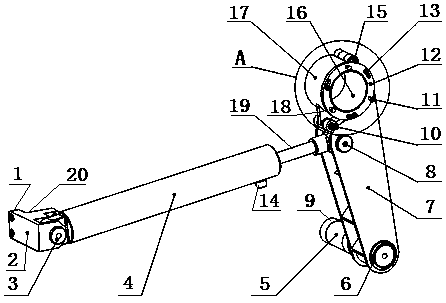
[0028] Specific embodiments of the present invention, such as Figure 1-11 As shown, a disassembly and assembly device for an oil roll is characterized in that: it consists of a hydraulic transmission mechanism, a crank transmission mechanism and a fixed connection mechanism. The fixed connection mechanism is respectively arranged at the bottom of the hydraulic transmission mechanism and the crank transmission mechanism. The hydraulic transmission mechanism Set on the upper part of the crank transmission mechanism, wherein,

[0029] A. The hydraulic transmission mechanism consists of a double-acting cylinder (4), a piston rod (19) that cooperates with the double-acting cylinder (4), a cylinder tailstock (2) and a pin shaft (3), and the cylinder tailstock (2) passes through The pin shaft (3) is hinged to the front end of the double-acting oil cylinder (4), and the rear part of the piston rod (19) is connected to the hydraulic arm of the crank transmission mechanism through the p...


PUM


Abstract

The present invention relates to a mounting and dismounting device for an oil material roller. The mounting and dismounting device is characterized by comprising hydraulic transmission, crank transmission and fixed connection mechanisms; the hydraulic transmission mechanism comprises a double-acting cylinder (4), a piston rod (19) cooperating with the double-acting cylinder (4) to act, a cylinder tailstock (2) and a hinge pin (3); and the crank transmission mechanism comprises a hydraulic rotating arm (7), a roller adjusting shaft sleeve (12), a supporting shaft (5), a large check ring (6), an arc-shaped cover (17), a chuck (18), a bolt (10), a jackscrew (11), nuts (13) and studs (23), and besides, a structure that a connecting rod (27) is arranged at the upper part of the hydraulic rotating arm (7) to replace the roller adjusting shaft sleeve (12), the jackscrew (11), nuts (13) and studs (23) is adopted by the mechanism. The mounting and dismounting device has the characteristics of safe and stable structure, safety and accuracy in mounting and dismounting, high quality and efficiency, low cost and the like.

Description

technical field [0001] The invention relates to the technical field of tools or devices for removing and installing oil rolls of oil flaking mechanical equipment such as hydraulic crushers, in particular to a dismantling device for oil rolls. Background technique [0002] As we all know, there are many types of oil flaking machinery and equipment such as hydraulic crushers at home and abroad, and the most used crushers or flaking machines include double-roll and double-roll flaking machines. The former is inconvenient to adjust due to the small pressure between the rolls, and the effect of crushing or flaking is not good; the latter has a large unit processing capacity due to the high pressure between the rolls and the high speed. The existing various crushers or flaking machines generally have low output, poor crushing or flaking effect, unstable hydraulic system, especially many faults, and easy wear of the transmission belt (especially vertical transmission). It is diffi...

Claims


Application Information

Patent Timeline
Patent Type & Authority Patents(China)
IPC IPC(8): B25B27/14
Inventor 刘小华刘立新薛长安陈哲董志海
Owner ZHAODONG DONG LONG SAVING ENERGY NEW TECH
Why Eureka
Try Eureka