
A floating ball automatic ink filling device

An automatic ink filling and floating ball technology, applied in printing, printing machines, general parts of printing machinery, etc., can solve problems such as overflow, ink addition, waste, etc.

Inactive Publication Date: 2017-12-15
TAICANG XINHE PRINTING & PACKAGING
View PDF5 Cites 0 Cited by
  • Summary
  • Abstract
  • Description
  • Claims
  • Application Information

AI Technical Summary

Problems solved by technology

[0002] In the field of printing, the ink required for printing is usually supplied and supplemented by an oil supply pump, that is, an oil supply pump is set on one side of each printing area to pump ink to the ink cartridge. If the ink sent into the ink cartridge exceeds a certain liquid Under the influence of the force generated when the printing roller group rotates, the ink in the ink cartridge will fluctuate, and even overflow the ink cartridge, which not only causes waste, but also affects the working environment. Once it splashes on the surface of the paper, It will affect the printing quality, and most of the current ink adding systems of printing machines are added in segments. When the ink cartridge reaches a certain position, it is added, and the ink cannot be added in time, which makes the resistance of the printing roller fluctuate greatly and affects the printing machine. Part life

Method used


Image

  • A floating ball automatic ink filling device
  • A floating ball automatic ink filling device

Examples


Embodiment Construction

[0019] The present invention will be further described below in conjunction with the accompanying drawings.

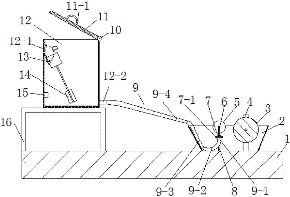
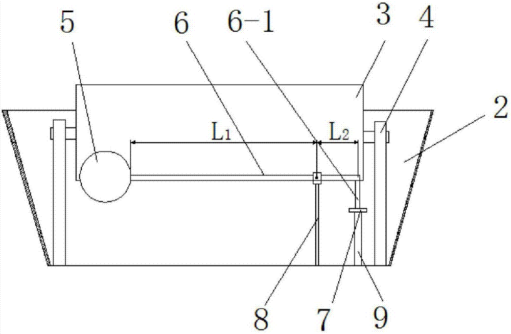
[0020] Such as figure 1 and 2 As shown, the ink cartridge 2 of the present invention is arranged on the upper surface of the base 1; the printing roller 3 is fixedly connected to the upper end of the printing roller holder 4; the lower end of the printing roller holder 4 is connected to the ink cartridge The upper surface of the inner cavity of 2 is connected and fixed; the platform feet of the support platform 16 are fixedly connected with the upper surface of the base 1; the bottom of the ink barrel 12 is fixedly connected with the upper surface of the support platform 16; the bung 11 edge It is hinged with the outer edge of the ink barrel 12 through the hinge shaft 10; the upper surface of the barrel lid 11 is provided with a barrel lid handle 11-1; the ink barrel 12 is provided with a motor 13; the motor 13 is provided with an impeller 14; The lower end of the su...


PUM


Abstract

The invention relates to the technical field of printing, in particular to a floating ball automatic ink adding device. The floating ball automatic ink adding device comprises a printing ink box floating ball, a floating arm, a support rod, an ink supplementing pipe and an ink bucket. A liquid level alarm is arranged at the lower end of the surface of an inner cavity of the ink bucket. A short inclined pipe and the left side surface of an inner cavity of a printing ink box are mutually and fixedly connected. The ink inlet end of a long inclined pipe and the outlet end of an ink outlet connector communicate with each other. One end of the floating arm and the floating ball are mutually and fixedly connected. A pressing rod is arranged at the other end of the floating arm. One end of the support rod and the upper surface of the inner cavity of the printing ink box are mutually and fixedly connected. The other end of the support rod is hinged to the right side of the floating arm. When the floating ball automatic ink adding device is used, when the depth of printing ink is reduced, the floating ball moves downwards, a copper valve is opened, and the printing ink is supplemented. According to the design, ink supplementing response speed is high, so that the printing ink level of the printing ink box is more stable, the printing quality of a printing machine is higher, and the life of parts is longer. The floating ball automatic ink adding device has the advantages of being simple in structure, reasonable in arrangement, low in manufacturing cost and the like.

Description

technical field [0001] The invention relates to the technical field of printing, in particular to a floating ball automatic ink filling device. Background technique [0002] In the field of printing, the ink required for printing is usually supplied and supplemented by an oil supply pump, that is, an oil supply pump is set on one side of each printing area to pump ink to the ink cartridge. If the ink sent into the ink cartridge exceeds a certain liquid Under the influence of the force generated when the printing roller group rotates, the ink in the ink cartridge will fluctuate, and even overflow the ink cartridge, which not only causes waste, but also affects the working environment. Once it splashes on the surface of the paper, It will affect the printing quality, and most of the current ink adding systems of printing machines are added in segments. When the ink cartridge reaches a certain position, it is added, and the ink cannot be added in time, which makes the resistanc...

Claims


Application Information

Patent Timeline
Patent Type & Authority Patents(China)
IPC IPC(8): B41F31/02
CPCB41F31/02B41F31/022
Inventor 蒋冬艳
Owner TAICANG XINHE PRINTING & PACKAGING
Learn More