Droplet capture chip and microfluidic chip

A microfluidic chip and droplet technology, applied in chemical instruments and methods, biochemical equipment and methods, enzymology/microbiology devices, etc., can solve problems such as increasing the tedious operation, increasing the operation time, and increasing the cost of the instrument. , to achieve fast and fully integrated automatic detection, reduce intermediate links, and speed up analysis

Inactive Publication Date: 2016-07-27
SHENZHEN INST OF ADVANCED TECH CHINESE ACAD OF SCI
View PDF4 Cites 19 Cited by
  • Summary
  • Abstract
  • Description
  • Claims
  • Application Information

AI Technical Summary

Problems solved by technology

Bio-Rad's droplet PCR instrument operates differently from droplet generation, nucleic acid amplification, and fluorescence detection, which increases the comple

Method used


Image

  • Droplet capture chip and microfluidic chip
  • Droplet capture chip and microfluidic chip
  • Droplet capture chip and microfluidic chip

Examples


Embodiment 1

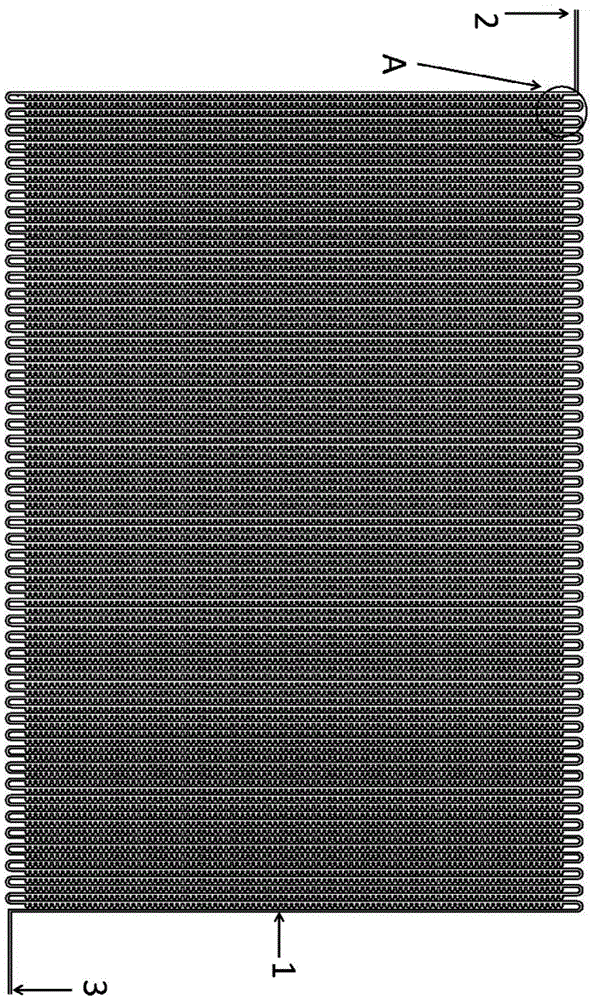
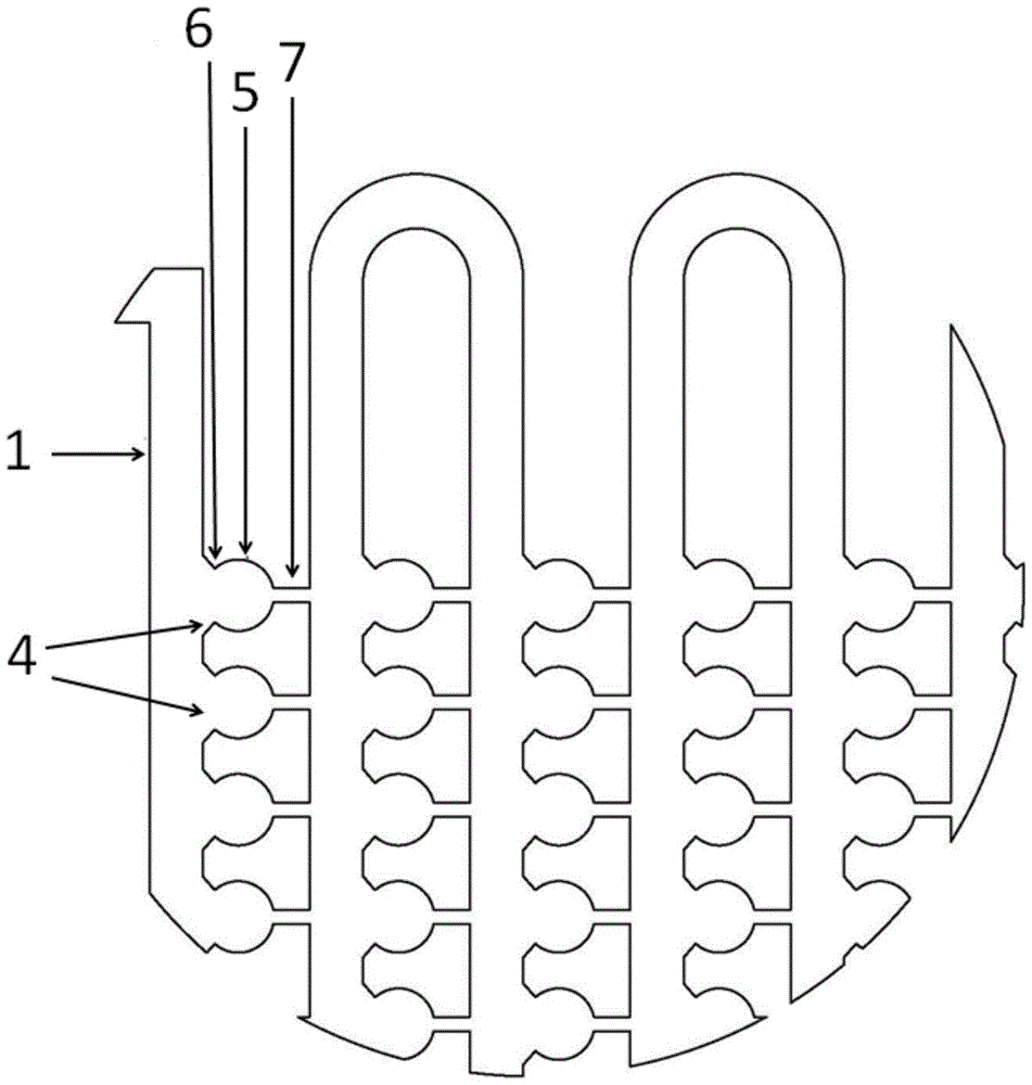
[0048] An embodiment of the droplet capture chip of the present invention, such as figure 1 with 2 As shown, the droplet capture chip includes a fluidic microchannel 1, the fluidic microchannel 1 has a droplet inlet 2 and a droplet outflow 3, wherein a plurality of branches are formed at intervals along the fluidic microchannel 1 4. The branch 4 is extended to form a droplet trapping chamber 5 , and the droplet trapping chamber 5 has a droplet inlet port 6 and a droplet outflow suppression port 7 sequentially extending from the branch path 4 .

[0049] Preferably, there are a plurality of fluid microchannels 1, and the plurality of fluid microchannels 1 are arranged in parallel and in fluid communication with each other.

[0050] Preferably, the droplet-inhibiting outflow end 7 of the droplet trapping chamber 5 communicates with the adjacent downstream fluidic microchannel 1 .

[0051] In order to achieve the above purpose, the inventors conducted research on the size of the...

Embodiment 2

[0056] An embodiment of the microfluidic chip of the present invention, such as Image 6 with Figure 7 As shown, the microfluidic chip includes the droplet capture chip described in Embodiment 1, and the microfluidic chip also includes a droplet generation chip, and the droplet generation chip includes a droplet generation area 10, a first step Liquid channel 11, the second liquid inlet channel 12 and liquid outlet channel 13; One end of the first liquid inlet channel 11, one end of the second liquid inlet channel 12 and one end of the liquid outlet channel 13 converge in the droplet generation area 10, the other end of the first liquid inlet channel 11 is provided with a first liquid inlet 8, the other end of the second liquid inlet channel 12 is provided with a second liquid inlet 9, and the liquid outlet channel 13 The other end communicates with the droplet inlet 2 of the fluidic microchannel 1 of the droplet capture chip. For the communication between the first liquid ...


PUM

PropertyMeasurementUnit
Diameteraaaaaaaaaa

Abstract

The invention provides a droplet capture chip. The droplet capture chip has the beneficial effects that a plurality of droplet capture chambers are arranged in the droplet capture chip, so that droplets can directly undergo in situ amplification and in situ detection after being captured; droplet generation and droplet capture are integrated on one microfluidic chip, so that convenient and rapid totally integrated automation detection is achieved, the intermediate links can be reduced and the analysis speed can be increased; the imaging information of the droplet capture chip is directly captured with a CCD (charge-coupled device), the CCD is simple and is easy to operate, and the accuracy rate of the obtained result is high; high-sensitivity detection can be achieved by scanning each fixed droplet by laser-induced fluorescence; the droplet capture chip and the microfluidic chip can make up for the deficiency of the detection technology of existing blood circulation DNA mutation, can achieve more sensitive simultaneous detection of multiple mutations and have great significance in increasing the clinical application value of blood circulation DNA in tumor diagnosis and therapy.

Description

technical field [0001] The invention relates to a chip, in particular to a droplet capture chip and a microfluidic chip. Background technique [0002] Microfluidic chip technology is a rapidly developing high-tech and one of the frontier fields of multidisciplinary interdisciplinary technology. It is an important technology platform for signal detection in life sciences, chemical sciences and information sciences. It refers to the integration of basic operating units such as sample preparation, reaction, separation, and detection involved in the fields of biology and chemistry into a chip of several square centimeters (or even smaller), and a network of microchannels is formed to control fluid flow. A technology that replaces various functions of a conventional biological or chemical laboratory throughout the system. After two decades of development, the microfluidic chip laboratory has been listed as one of the most important cutting-edge technologies in the world in the 2...

Claims


Application Information

Patent Timeline
IPC IPC(8): C12M1/34C12M1/00B01L3/00
CPCC12Q1/6851B01L3/5027C12Q2531/113C12Q2563/159
Inventor 於林芬吴天准李丽军
Owner SHENZHEN INST OF ADVANCED TECH CHINESE ACAD OF SCI
Why Eureka
Try Eureka