Anti-burglary locking-controlled ball check valve
A check ball valve and lock control technology, which is applied to control valves, devices to prevent accidental or unauthorized actions, valve details, etc., can solve the problem of check ball valves lacking anti-theft dismantling joints, etc., and eliminate the hidden danger of screw loss , fast unlocking and high locking reliability
- Summary
- Abstract
- Description
- Claims
- Application Information
AI Technical Summary
Problems solved by technology
Method used
Image
Examples
Embodiment 1
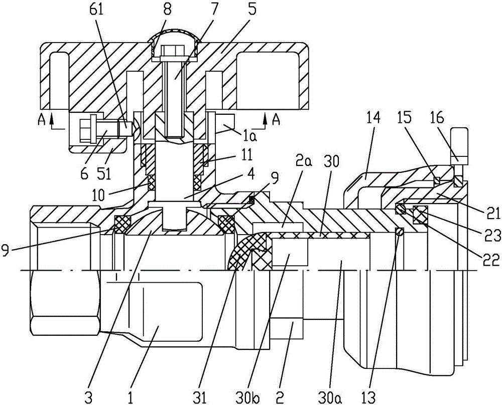
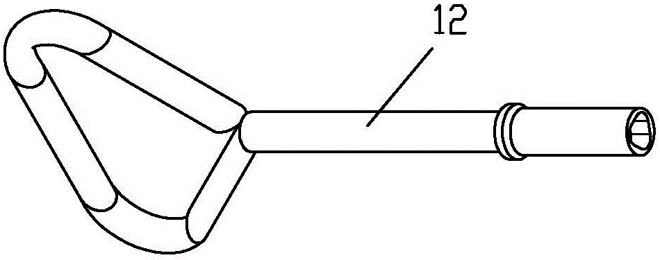
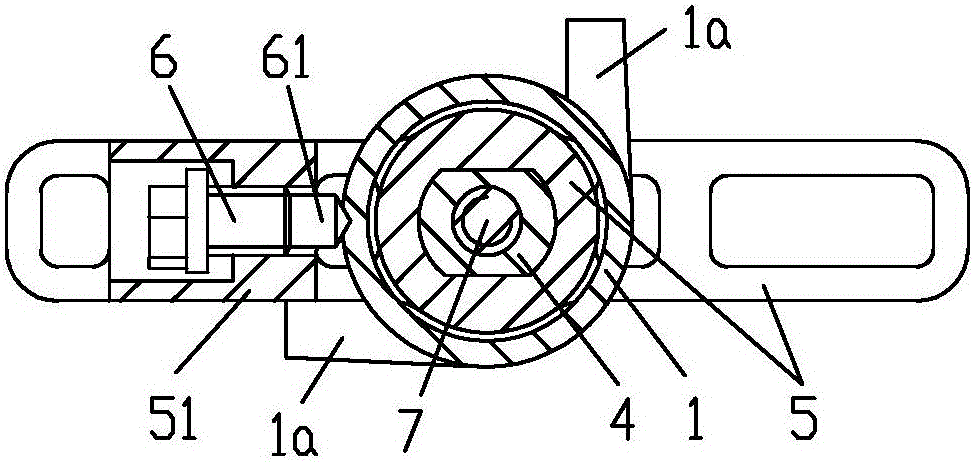
[0022] Example 1, see figure 1 , figure 2 , image 3, an anti-theft dismantling control check ball valve, comprising a valve body 1 and a valve cover 2, the external interface of the valve cover 2 constitutes the structure of an anti-theft disassembly joint, and a check valve structure is formed on the fluid passage of the valve cover 2; the valve body 1 and the bonnet 2 are connected with the valve core 3 through the sealing seat ring 9, and the valve core 3 is connected with the wrench 5 through the valve stem 4; one side of the valve body 1 is formed with a stuffing chamber, and the valve stem 4 is located in the stuffing chamber, and the valve A sealing packing 10 is provided between the outer circumference of the rod 4 and the inner wall of the stuffing chamber, and the sealing packing 10 is compressed by the packing nut 11 to form a sealed connection between the valve rod 4 and the valve body 1; the wrench 5 is T-shaped, and the wrench 5 passes through the T The verti...
Embodiment 2
[0026] Example 2, see Figure 4 , the locking screw 6 is screwed on the outer wall of the stuffing chamber of the valve body 1, and the limit stop tongue 51 is located outside the head of the lock screw 6, so that when the lock screw 6 is tightened, the wrench 5 can rotate, and the limit stop tongue There is a perforation 52 horizontally on the 51, and the diameter of the perforation 52 is larger than the outer diameter of the screw opening tool 12 that can be inserted into the section, so that the locking screw 6 can be turned by the screw opening tool 12, so that the head of the locking screw 6 can extend into a part of the perforation 52, Thereby, the locking of the wrench 5 is formed; or, the locking screw 6 is twisted by the screw opening tool 12, so that the head of the locking screw 6 escapes from the perforation 52 and is positioned inside the limit stop tongue 51, thereby releasing the locking state of the wrench 5.
[0027] The rest of the structure of this embodimen...
Embodiment 3
[0028] Example 3, see Figure 5 , Image 6 , the head 61 of the locking screw 6 is formed with a triangular hole-shaped tightening structure, so as to be screwed only by the screw opening tool 12a matched therewith, and the screw opening tool 12a has a tightening structure with the front end of the locking screw 6 Matching triangular prism-shaped head.
[0029] The rest of the structure of this embodiment is the same as that of Embodiment 1, and will not be repeated here.
PUM
 Abstract
Description
Claims
Application Information
 - R&D
- Intellectual Property
- Life Sciences
- Materials
- Tech Scout
- Unparalleled Data Quality
- Higher Quality Content
- 60% Fewer Hallucinations
Browse by: Latest US Patents, China's latest patents, Technical Efficacy Thesaurus, Application Domain, Technology Topic, Popular Technical Reports.
© 2025 PatSnap. All rights reserved.Legal|Privacy policy|Modern Slavery Act Transparency Statement|Sitemap|About US| Contact US: help@patsnap.com


