Dimmable LED light source

A technology of LED light source and LED chip, which is applied in the field of LED light source, can solve the problems such as unsatisfactory dimming and color adjustment, and achieve the effect of avoiding heat loss, simple realization and convenient manufacture

Inactive Publication Date: 2016-07-27
SICHUAN SUNFOR LIGHT +1
View PDF6 Cites 4 Cited by
  • Summary
  • Abstract
  • Description
  • Claims
  • Application Information

AI Technical Summary

Problems solved by technology

However, in practice, it is found that different wavelength chips have an impact on the color temperature change of the light source, but not as much as the phosphor powder change, so it is not ideal to achieve dimming and color adjustment through different chip wavelengths

Method used


Image

  • Dimmable LED light source
  • Dimmable LED light source
  • Dimmable LED light source

Examples


Embodiment 1

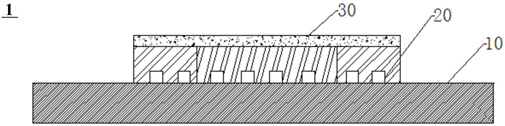
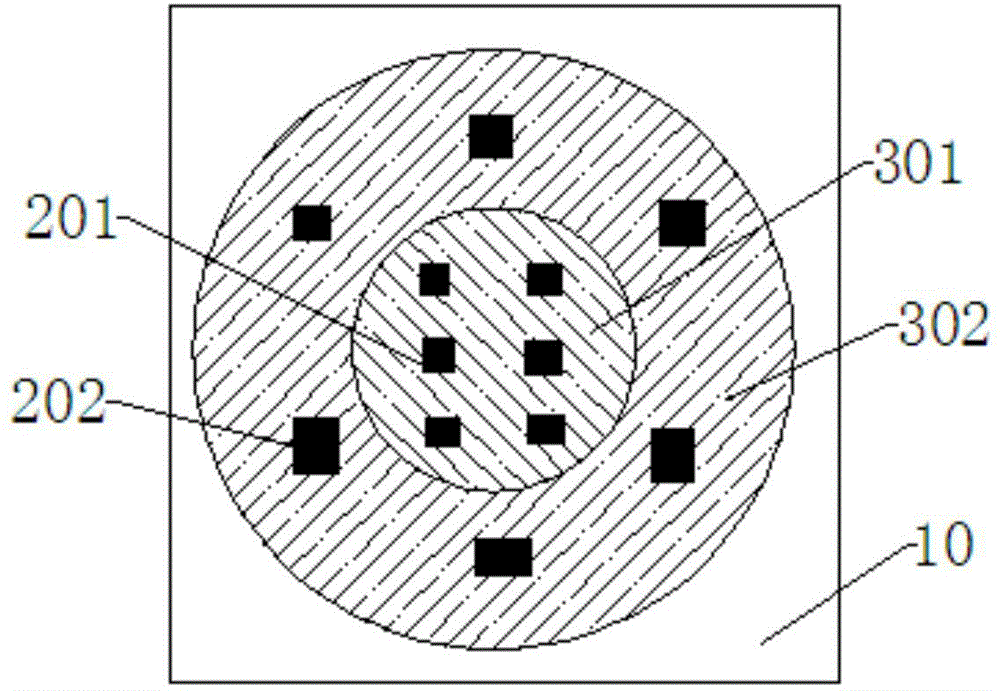
[0063] figure 2 It is a structural schematic diagram of Embodiment 1 of the present invention; image 3 It is a top view of Embodiment 1 of the present invention. figure 2 and image 3 A preferred dimmable LED light source 1 of the present invention is shown, and a first LED chip group 201 and a second LED chip group 202 are arranged on a substrate 10 . Wherein, the LED chip is preferably a blue LED chip. And the first LED chip group 201 and the second LED chip group 202 are arranged on the substrate 10 through COB packaging. The first LED chip group 201 is disposed on the central area of ​​the substrate 10 , and the second LED chip group 202 is disposed around the first LED chip group 201 . Preferably, the annular light emitting area formed by the second LED chip group 202 surrounds the solid circular light emitting area formed by the first LED chip group 201 in a concentric manner. see image 3 , the ring-shaped light emitting area corresponds to the first color area...

Embodiment 2

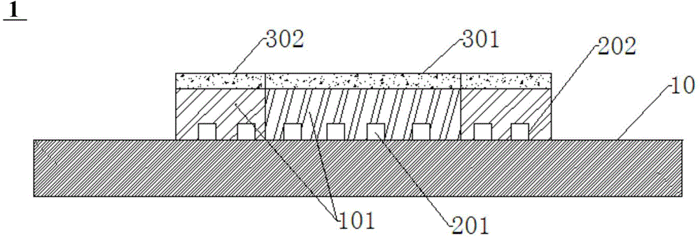
[0073] Such as Figure 4 As shown, the main difference between this embodiment and embodiment 1 is that the phosphor film 30 is divided into a first color region 301 and a second color region 302 . The first color region 301 includes two parts distributed on the phosphor film 30 in a cross shape. At this time, a second color region 302 is formed in a region between two parts of the first color region 301 distributed in a cross shape.

[0074] The first LED chip group 201 and the second LED chip group 202 are correspondingly disposed on the substrate 10 corresponding to the first color region 301 and the second color region 302 . Except for the above differences, other structures of this embodiment are the same as those of Embodiment 1.

[0075] In this embodiment, by adjusting the first adjustment switch K1 and the second adjustment switch K2 of the drive circuit, only one set of LED chipsets can be turned on selectively, or two sets of LED chipsets can be turned on at the s...

Embodiment 3

[0080] Such as Figure 5 As shown, the main difference between this embodiment and Embodiment 1 is that the phosphor film 30 includes a first color region 301 , a second color region 302 and a third color region 303 respectively distributed in a fan shape. The first color region 301 , the second color region 302 and the third color region 303 are joined together to form a circular phosphor film 30 .

[0081] The first LED chip group 201 , the second LED chip group 202 and the third LED chip group 203 are respectively disposed on the substrate 10 corresponding to the first color region 301 , the second color region 302 and the third color region 303 . Except for the above differences, other structures of this embodiment are the same as those of Embodiment 1.

[0082] In this embodiment, by adjusting the first adjustment switch K1, the second adjustment switch K2 and the third adjustment switch K3 of the drive circuit, only one group of LED chips can be turned on selectively, a...


PUM


Abstract

The invention relates to a dimmable LED light source. The LED light source comprises a fluorescent powder film with at least two color zones and an LED module driven by a driving circuit and comprising a plurality of independent chip sets, wherein the fluorescent powder film and the LED module are arranged at an interval in a detachable manner or integrally forming manner, and the at least two color zones of the fluorescent powder film are arranged in a manner of separately corresponding to one LED chip set of the LED module in space, so that the LED light source can emit light rays with at least two color temperatures and / or colors only by the control over the driving circuit. According to the invention, by correspondingly arranging the fluorescent powder film zones with different colors on the LED chip sets with different color temperatures, the fluorescent powder film of the LED light source can be combined with the LED chip sets with different color temperatures according to requirements to emit light rays with different color temperatures and / or colors, and by independently adjusting currents of multiple LED chip sets, dimming and color matching of the LED light source can be further achieved.

Description

technical field [0001] The invention relates to the field of LED lighting, in particular to a dimmable LED light source. Background technique [0002] Light-emitting diodes have gradually replaced traditional light sources such as fluorescent lamps and incandescent lamps, and have gradually entered human life due to their energy-saving, environmental protection, and long-life characteristics. Most of the LED lamps seen at present use white LED lamp beads as light sources. There are two ways to obtain a white LED light source: one is to directly coat the phosphor powder on the blue LED chip; the other is to make the phosphor powder into a phosphor film through a specific process and place it on top of the LED chip to produce white light through superimposition. light source. The former seriously affects the life of the LED due to the easy denaturation and failure of the phosphor powder at high temperature; the latter phosphor powder is far away from the LED heat source, wil...

Claims


Application Information

Patent Timeline
Patent Type & Authority Applications(China)
IPC IPC(8): F21S2/00F21V19/00F21V23/00F21Y101/02
CPCF21S2/00
Inventor 王森赵昆黄德忠余镜石固坚
Owner SICHUAN SUNFOR LIGHT
Why Eureka
Try Eureka