
Optical lens and electronic equipment applying same

A technology of optical lens and lens barrel, which is applied in the field of optics, can solve the problems of less glue dispensing and water ingress in the lens, and achieve the effect of increasing the contact area and avoiding water ingress in the lens

Inactive Publication Date: 2016-07-27
GUANGDONG XUYE OPTOELECTRONICS TECH
View PDF5 Cites 5 Cited by
  • Summary
  • Abstract
  • Description
  • Claims
  • Application Information

AI Technical Summary

Problems solved by technology

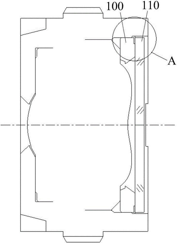
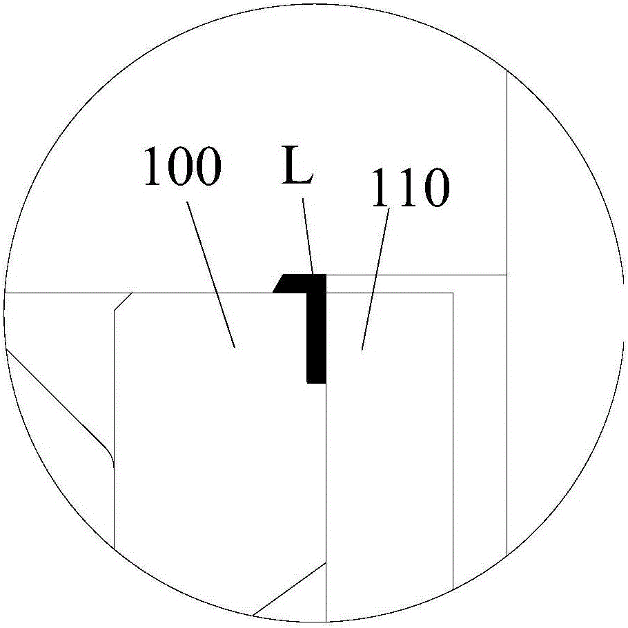
[0004] In view of this, the present invention provides an optical lens and an electronic device using the optical lens to solve the problem in the prior art that an effective sealing glue space is not formed between the stopper 100 and the filter 110 The problem of water entering the lens during the cleaning process when the dispensing amount is small or improper

Method used


Image

  • Optical lens and electronic equipment applying same
  • Optical lens and electronic equipment applying same
  • Optical lens and electronic equipment applying same

Examples


Embodiment Construction

[0026] The technical solutions in the embodiments of the present invention will be clearly and completely described below in conjunction with the accompanying drawings in the embodiments of the present invention. Obviously, the described embodiments are only a part of the embodiments of the present invention, rather than all the embodiments. Based on the embodiments of the present invention, all other embodiments obtained by those of ordinary skill in the art without creative work shall fall within the protection scope of the present invention.

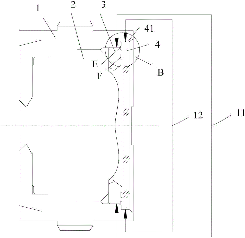
[0027] The embodiment of the present invention provides an optical lens. The optical lens in this embodiment is limited to a COB packaged optical lens, such as image 3 As shown, the optical lens includes a lens barrel 1 and at least one circular lens 2, a black annular stopper 3, and a circular filter 4 sequentially arranged in the lens barrel 1 from the object side to the image side. In the present invention, the shapes of the circular ...


PUM

PropertyMeasurementUnit
Lengthaaaaaaaaaa
Lengthaaaaaaaaaa

Abstract

The invention provides an optical lens and electronic equipment applying the same.The optical lens comprises a lens barrel and at least one lens body, a stop part and an optical filter which are sequentially arranged in the lens barrel from the object side to the image side; the outer diameter of the optical filter is larger than that of the stop part, and a glue dispensing groove protruding towards the object side is formed among the optical filter, the lens barrel and the stop part and used for containing glue, so that the stop part, the optical filter and the lens barrel are tightly fixed by means of the glue.Due to the fact that the outer diameter of the optical filter is larger than that of the stop part, and the glue dispensing groove protruding towards the object side is formed among the optical filter, the lens barrel and the stop part, a space capable of effectively sealing the glue is formed between the optical filter and the stop part, the contact area of the optical filter and the glue is increased by means of the glue dispensing groove, and the problem that due to the fact that the glue dispensing quantity is low or glue dispensing is improper, water enters the lens in the cleaning process can be avoided.

Description

Technical field [0001] The present invention relates to the field of optical technology, and more specifically, to an optical lens and an electronic device using the optical lens. Background technique [0002] In the manufacturing process of the optical lens, it is necessary to load the lens, the stopper, and the light-shielding film in the lens barrel in sequence. Among them, the packaging process of the imaging chip in the optical lens mainly includes a CSP (ChipSize Package) packaging process and a COB (ChiponBoand, chip-on-board) packaging process. Compared with the CSP packaging process, the COB packaging process has a lower packaging cost, so the COB packaging process is more widely used. [0003] Furthermore, the optical lens adopting the COB packaging process after loading is completed, such as figure 1 with figure 2 As shown, it is necessary to inject glue into the gap L between the stopper 100 and the filter 110 to prevent the filter 110 and other components from being ...

Claims


Application Information

Patent Timeline
IPC IPC(8): G02B7/00G02B5/20G03B30/00
CPCG02B7/00G02B7/006G02B5/20
Inventor 林肖怡袁正超任媛陈健鹏马晶晶
Owner GUANGDONG XUYE OPTOELECTRONICS TECH
Learn More