Alarm device based on WiFi networking design and with environmental vibration testing function
A technology for vibration detection and alarms, which is applied in the direction of electric alarms, alarms, anti-theft alarms, etc., can solve the problems of expensive RFID tags, and achieve the effects of reducing power consumption, application safety, and convenient wireless connection and communication
- Summary
- Abstract
- Description
- Claims
- Application Information
AI Technical Summary
Problems solved by technology
Method used
Image

Examples
Embodiment 1
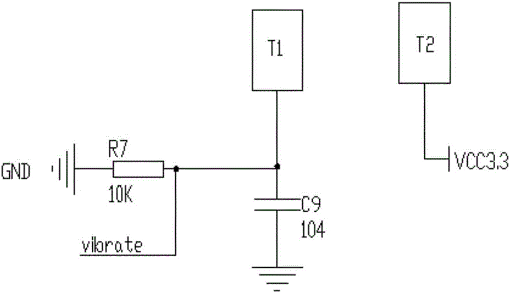
[0040] An alarm with environmental vibration detection function designed based on WiFi networking, such as figure 1 , figure 2 , image 3 , Figure 4 , Figure 5 , Figure 6 , Figure 7 , Figure 8 , Figure 9 As shown, an environmental vibration detection circuit, a touch driving circuit, an alarm circuit and a WiFi module circuit are provided, and the alarm circuit is connected with the environmental vibration detection circuit, the touch driving circuit and the WiFi module circuit respectively, and the environmental vibration detection circuit There are measuring point T1, measuring point T2, capacitor C9, and resistor R7 inside. The second end of the resistor R7 is respectively connected to the first end of the capacitor C9, the measuring point T1 and the alarm circuit. The second end of the resistor R7 One end and the second end of the capacitor C9 are all connected to the ground, and the measuring point T2 is connected to the alarm circuit; the WiFi module circui...
Embodiment 2
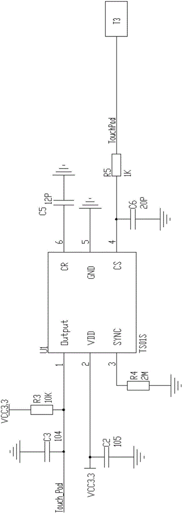
[0044] This embodiment is further optimized on the basis of the above embodiments, such as figure 1 , figure 2 , image 3 , Figure 4 , Figure 5 , Figure 6 , Figure 7 , Figure 8 , Figure 9 As shown, further in order to better realize the present invention, the following arrangement structure is particularly adopted: the touch drive circuit is provided with capacitor C3, capacitor C2, capacitor C5, capacitor C6, resistor R3, resistor R4, resistor R5 and touch The processor chip U1, the Output pin of the touch processor chip U1 are respectively connected to the second end of the resistor R3, the second end of the capacitor C3 and the alarm circuit, the first end of the capacitor C3 is grounded, and the first end of the resistor R3 is connected to the alarm circuit. The alarm circuit is connected, the VDD pin of the touch processor chip U1 is respectively connected to the first end of the capacitor C2 and the alarm circuit, and the second end of the capacitor C2 is g...
Embodiment 3
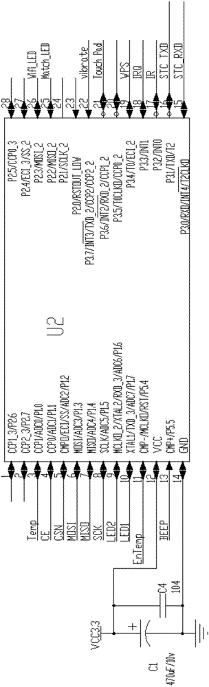
[0048] This embodiment is further optimized on the basis of any of the above embodiments, such as figure 1 , figure 2 , image 3 , Figure 4 , Figure 5 , Figure 6 , Figure 7 , Figure 8 , Figure 9 As shown, further in order to better realize the present invention, the following setting structure is adopted in particular: the alarm circuit includes a processor chip circuit, an indicator light interface circuit, a 2.4G module circuit, a power supply and a sound alarm circuit, and the processor The chip circuit is connected to the indicator light interface circuit, 2.4G module circuit, sound alarm circuit, WiFi interface P1, the Output pin of the touch processor chip U1 and the power supply, and the power supply is also connected to the 2.4G module circuit, sound alarm circuit, touch processor The VDD pin of the chip U1, the first end of the resistor R3, and the first end of the resistor R28.
PUM
 Abstract
Description
Claims
Application Information