
Bypass protection device for high-voltage DC circuit breaker and protection method thereof

A technology of bypass protection and high-voltage direct current, applied in the direction of emergency protection circuit devices, electrical components, etc., can solve the problems of non-protection methods and the influence of arrester absorption capacity, etc., and achieve the effect of simple installation, easy modular design, and novel structure

Active Publication Date: 2016-07-27
STATE GRID CORP OF CHINA +2
View PDF5 Cites 9 Cited by
  • Summary
  • Abstract
  • Description
  • Claims
  • Application Information

AI Technical Summary

Problems solved by technology

[0003] The conventional bypass protection method is to connect arresters in parallel at both ends of the protected equipment, but the operation of the arrester needs to absorb the loop current, and the high-voltage DC circuit breaker has a large capacity, which has a high impact on the absorption capacity of the arrester.
In addition, since the voltage at both ends of the circuit breaker is only several thousand volts, there are few surge arresters that match such a low voltage and have high energy absorption capacity, so it is not a more economical protection method

Method used


Image

  • Bypass protection device for high-voltage DC circuit breaker and protection method thereof
  • Bypass protection device for high-voltage DC circuit breaker and protection method thereof
  • Bypass protection device for high-voltage DC circuit breaker and protection method thereof

Examples


Embodiment Construction

[0029] The specific implementation manners of the present invention will be further described in detail below in conjunction with the accompanying drawings.

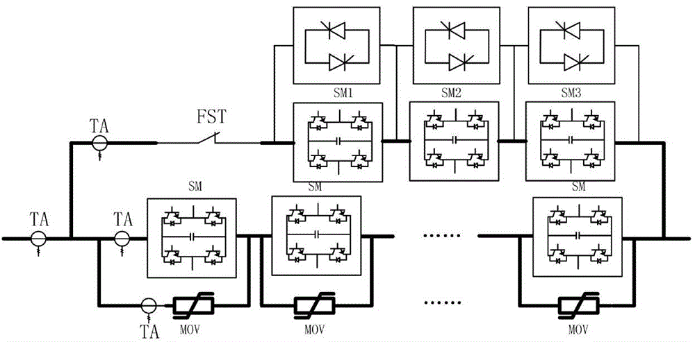
[0030] The high-voltage DC circuit breaker includes a DC bus, a main branch, a transfer branch and a discharge branch; the main branch, the transfer branch and the discharge branch are connected in parallel to the DC bus; the topology of the high-voltage DC circuit breaker Figure such as figure 1 As shown, the main branch is composed of cascaded H-bridge sub-modules in series with mechanical switches. The H-bridge sub-module includes two phases and four bridge arms, and capacitors are connected in parallel between the two phases; each bridge arm has an IGBT device and Composed of anti-parallel diodes; the transfer branch is composed of cascaded H-bridge sub-modules, the H-bridge sub-module includes two phases and four bridge arms, and a capacitor is connected in parallel between the two phases; each bridge arm has The I...


PUM


Abstract

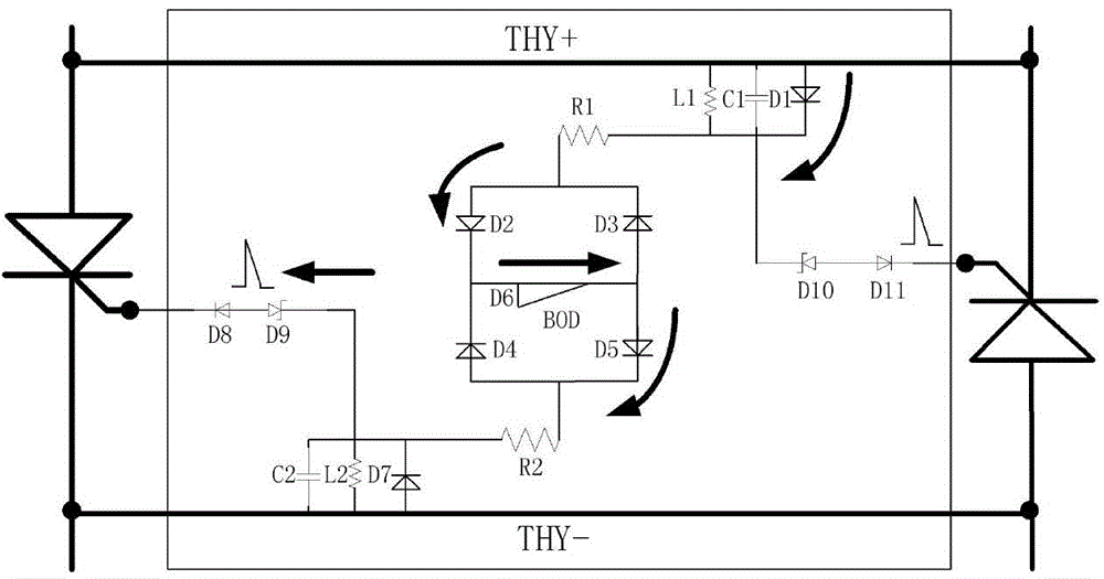
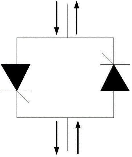
The invention relates to a bypass protection device for a high-voltage DC circuit breaker and a protection method thereof. The bypass protection device comprises a thyristor valve and a bridge type over-voltage protection circuit. The bridge type over-voltage protection circuit is connected between thyristors in anti-parallel connection with each other inside the thyristor valve. The two ends of each H-bridge sub-module of a main branch are connected in parallel with the thyristor valve. By means of the bypass protection device, during the abnormal shutting of the main branch of the circuit breaker, the circuit breaker is prevented from being damaged under the over-voltage effect of the sub-module. Namely, thyristors are connected in parallel with the sub-module of the main branch, wherein the thyristors are in compression joint in forward and reverse directions. During the normal operation, the current is switched on by a mechanical switch. During the occurrence of a fault, the current of the main branch is converted to the branch of a power electronic device in parallel connection with the main branch. After that, the current is switched off by the power electronic device. During the over-voltage period of the main branch, the thyristors are triggered, so that the current is enabled to pass through the thyristors to form a passageway. Therefore, the main branch is protected.

Description

technical field [0001] The invention relates to a protection device for a DC circuit breaker and a protection method thereof, in particular to a bypass protection device for a high-voltage DC circuit breaker and a protection method thereof. Background technique [0002] Compared with AC transmission, DC transmission has many advantages, such as low line loss, large transmission capacity, long transmission distance, and no problem of system synchronous operation stability. HVDC circuit breaker is a very important electrical component in HVDC converter station. For primary equipment, in the case of system failure or maintenance, the DC circuit breaker can change the structure of the power supply system without power failure to ensure the normal operation of the system. High-voltage DC circuit breakers can be roughly divided into mechanical high-voltage DC circuit breakers, all-solid-state high-voltage DC circuit breakers and hybrid high-voltage DC circuit breakers. Although t...

Claims


Application Information

Patent Timeline
Patent Type & Authority Applications(China)
IPC IPC(8): H02H7/00
Inventor 汤广福陈龙龙高阳孔德煜
Owner STATE GRID CORP OF CHINA
Learn More